




A microcontroller input sometimes changes state even when nobody is touching the circuit. A pushbutton may register a press by itself, or an unused GPIO pin may return different readings each time the program checks it. This behavior can come from a floating input.
A digital input needs a defined voltage to register a reliable HIGH or LOW state. A pull up resistor connects the signal to the positive supply, while a pull down resistor connects it to ground. Both establish a default logic state when another device is not actively controlling the signal.
You’ll find these resistors in Arduino projects, STM32 boards, pushbutton circuits, reset inputs and I²C communication networks. Their operation is simple, although selecting the right resistance takes a little calculation. These components are part of everyday analog and digital circuit design, particularly when a microcontroller needs a predictable input voltage.
What Is a Pull Up Resistor?
A pull up resistor connects a digital signal line to the positive supply voltage, usually called VCC. It keeps the signal HIGH when the connected device or switch leaves the line undriven.
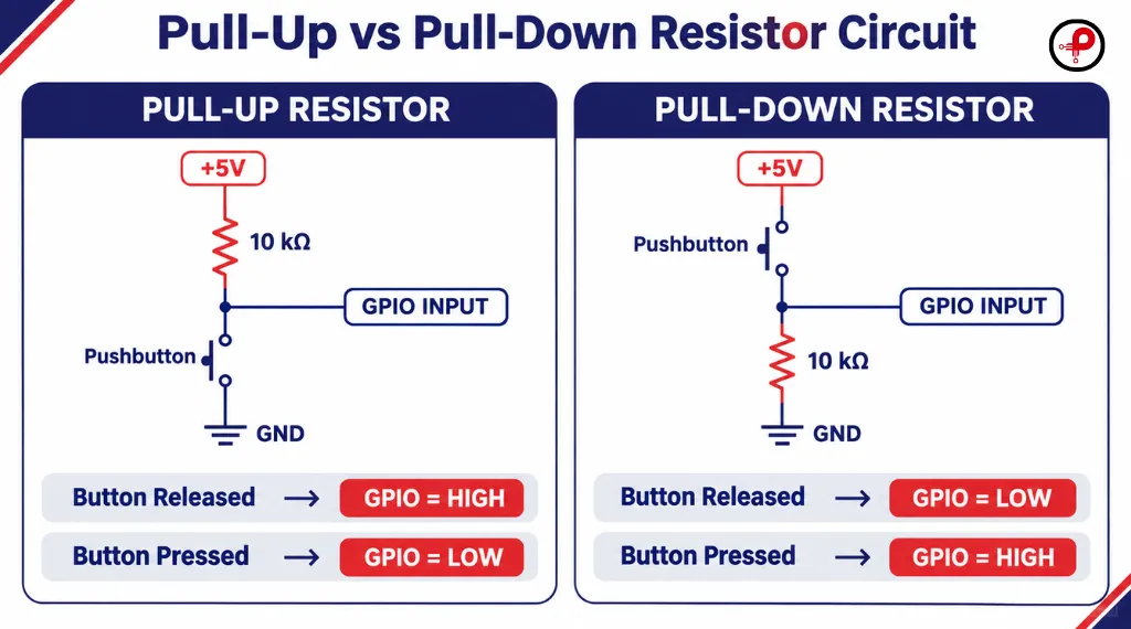
Consider a pushbutton connected to a microcontroller. One side of the button connects to ground, and the other side connects to a GPIO input. A resistor connects that same input to the positive supply. The GPIO reads HIGH while the button is released.
Press the button and the switch connects the input to ground. The reading changes to LOW. This is called an active-LOW button arrangement because pressing the button produces a LOW logic state.
Pull Up Resistor Circuit
          +5V
           |
         [10kΩ]
           |
           +---------- GPIO INPUT
           |
        PUSHBUTTON
           |
          GND
The resistor holds the input near +5 V when the button is open. Digital inputs normally draw very little current, so the voltage remains close to the supply level. When the switch closes, current flows through the 10 kΩ resistor and the switch to ground.
The resistor limits that current. Without it, the switch would connect +5 V directly to ground when pressed, creating a short circuit.
A 10 kΩ resistor is a common starting value for a basic pushbutton input. The right value still depends on the microcontroller’s electrical specifications and the circuit around the pin.
What Is a Pull Down Resistor?
A pull down resistor connects the signal line to ground. It keeps the input LOW while the switch is open or the external device leaves the signal undriven.
The button connects the GPIO input to the positive supply. With the button released, the resistor holds the input near 0 V. Pressing the button connects the input to +5 V, so the GPIO reads HIGH.
          +5V
           |
        PUSHBUTTON
           |
           +---------- GPIO INPUT
           |
         [10kΩ]
           |
          GND
The resistor also limits current when the button is pressed. In this arrangement, current flows from the supply through the switch and resistor to ground. A pull down circuit is useful when a control input should remain LOW until an external signal activates it.
You might use one on an enable input, a pushbutton or a digital control line. The choice depends on the default state required by the circuit. Check the input’s voltage limits before connecting the resistor to a supply rail.
Why Do Digital Inputs Need Pull Up and Pull Down Resistors?
A microcontroller input configured as a high-impedance input draws very little current. That makes it useful for sensing signals, but it also means an unconnected pin can have an undefined voltage.
This condition is called a floating input.
An unconnected GPIO may pick up electrical interference from nearby wires, switching circuits, motors or other sources of noise. Its voltage can drift across the device’s logic thresholds, producing unexpected HIGH and LOW readings.
For example, a program might read an unused input like this:
HIGH
LOW
HIGH
HIGH
LOW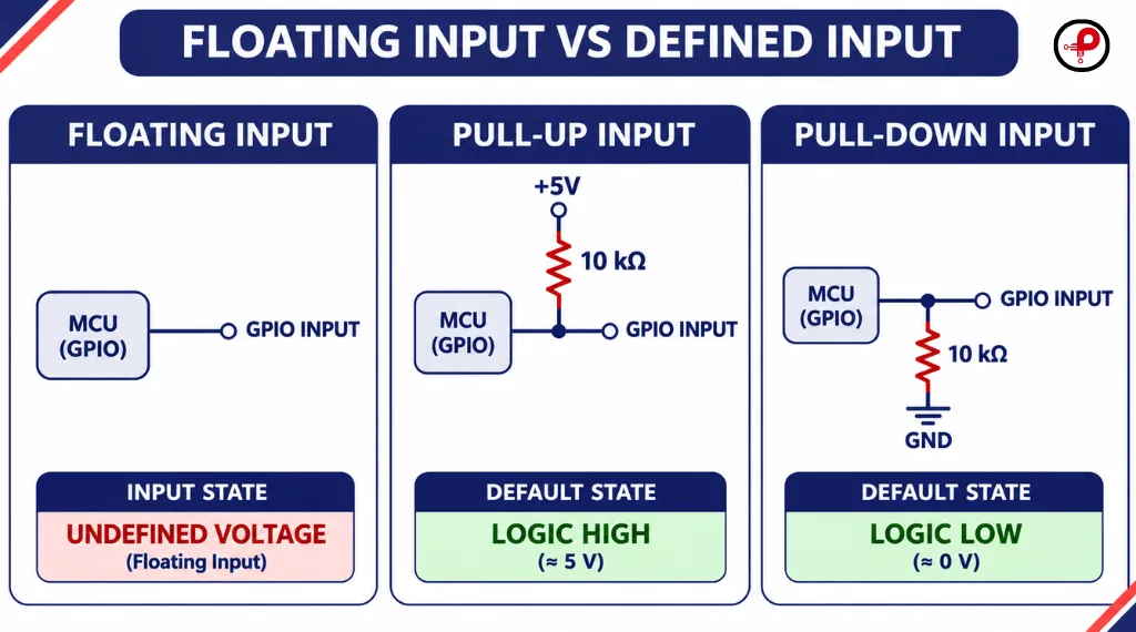
Those changes may come from interference rather than a real button press. A pull resistor gives the input a defined path, and the voltage settles toward the supply or ground depending on the circuit.
What Do HIGH and LOW Mean?
HIGH and LOW refer to voltage ranges. Their exact limits depend on the microcontroller or logic device. Two datasheet parameters are especially useful when selecting a resistor.
- VIH: Minimum input voltage guaranteed to be recognized as HIGH.
- VIL: Maximum input voltage guaranteed to be recognized as LOW.
For a 3.3 V microcontroller, the HIGH threshold may differ from the threshold on a 5 V device. Some pins also have strict limits on the voltage they can tolerate.
A pull up resistor connected to 5 V does not automatically make that signal safe for a 3.3 V-only input. Check the GPIO’s absolute maximum ratings and input-voltage specifications first. A resistor controls current in a circuit. It does not, by itself, provide voltage-level protection.
Pull Up vs Pull Down Resistor: Key Differences
Both resistors establish a default state, but they connect to opposite supply rails. The difference becomes clear when you examine the voltage at the input with the button released and pressed.
| Feature | Pull Up Resistor | Pull Down Resistor |
|---|---|---|
| Resistor connection | Signal to VCC | Signal to GND |
| Default input state | HIGH | LOW |
| Button connection | Input to GND | Input to VCC |
| Button released | HIGH | LOW |
| Button pressed | LOW | HIGH |
| Common logic arrangement | Active-LOW | Active-HIGH |
| Typical application | GPIO, reset and I²C | GPIO, enable and control inputs |
Pull Up and Pull Down Truth Table
For the two pushbutton circuits described above:
| Button condition | Pull up input | Pull down input |
|---|---|---|
| Released | HIGH | LOW |
| Pressed | LOW | HIGH |
This table is useful when writing firmware. With a pull up circuit, a pressed button returns LOW. Your program must account for that inverted logic. With a pull down circuit, pressing the button returns HIGH.
The default state also matters during startup. A reset or enable pin may need a known voltage before the microcontroller begins running its firmware.
How to Choose the Correct Pull Up or Pull Down Resistor Value
One question appears repeatedly in electronics forums and project discussions: should I use 1 kΩ, 4.7 kΩ, 10 kΩ or 100 kΩ?
There is no single value for every circuit. A resistor must be low enough to maintain a valid logic level while allowing the circuit to operate within its current and power limits.
For an ordinary pushbutton, 10 kΩ is a useful starting point. A communication bus such as I²C needs a more careful calculation. Component tolerance and power rating also matter, so our electronic component selection guidelines are useful when choosing the physical resistor for a design.
1. Calculate Current With Ohm’s Law
Consider a 5 V pull up circuit with a 10 kΩ resistor and a button connected to ground. When the button is pressed, the current is approximately:
I = 5 / 10,000 = 0.0005 A = 0.5 mA
The circuit draws approximately 0.5 mA through the resistor while the button is pressed, assuming the switch resistance is negligible. When the button is released, current is limited mainly by input leakage and any other connected loads.
2. Compare Common Resistor Values
The following table shows approximate current and resistor power for a 5 V supply. It assumes the switch connects the input directly to ground when pressed.
| Resistance | Current when pressed | Resistor power |
|---|---|---|
| 1 kΩ | 5 mA | 25 mW |
| 4.7 kΩ | 1.06 mA | 5.32 mW |
| 10 kΩ | 0.5 mA | 2.5 mW |
| 47 kΩ | 0.106 mA | 0.53 mW |
| 100 kΩ | 0.05 mA | 0.25 mW |
The power values come from P = V × I, assuming the full 5 V appears across the resistor. A 1 kΩ resistor provides a stronger pull up and draws 5 mA while the button is pressed. A 100 kΩ resistor draws far less current, although its weaker pull may be more affected by leakage and noise.
The choice depends on the input and wiring conditions.
3. Check Input Leakage Current
A microcontroller input is high impedance, but it is not a perfect open circuit. A small leakage current may flow into or out of the pin. That current can shift the voltage at the input.
For a pull up circuit, a simplified calculation is:
The resulting voltage must remain above the device’s minimum HIGH threshold.
For a pull down circuit, when leakage current flows into the input node:
The resulting voltage must remain below the maximum LOW threshold.
Use the worst-case leakage current and input thresholds from the component datasheet. The direction of leakage matters, so check the specified conditions instead of relying on a typical value.
4. Consider Capacitance and Signal Speed
A signal wire has capacitance. The GPIO input, PCB traces, cables and connectors all add to it. When a pull up resistor charges that capacitance, the voltage rises gradually.
The approximate RC time constant is:
A 10 kΩ resistor connected to 100 pF produces a time constant of:
The actual voltage rise follows an exponential curve. This delay is usually unimportant for a manually operated pushbutton, but it can affect faster digital signals and communication buses.
5. Check Current and Power Consumption
Battery-powered circuits need attention here. For a 3.3 V supply and a 10 kΩ pull up, the current is:
That current flows while the signal is held LOW. If several lines remain LOW for long periods, their combined consumption can affect battery life. For further design considerations, see our low-power circuit design guide.
A larger resistor reduces current. Check that the input still reaches a valid logic level under worst-case leakage and noise conditions.
Internal vs External Pull Up Resistors
Many microcontrollers contain internal pull up and pull down circuits. Firmware can enable them through the GPIO configuration. This saves PCB space and reduces the number of external components.
For a short pushbutton connection, an internal pull up may be all you need. Internal resistor values have a tolerance range, though. Their resistance can vary with the device and operating conditions, so check the datasheet before using one in a timing-sensitive circuit.
When an Internal Pull Up Is Suitable
An internal pull up is a convenient choice for a local pushbutton, a slow control input or a configuration switch. It also makes quick prototypes easier to wire.
When an External Resistor Is Needed
An external resistor gives you a defined resistance that you can select and measure. It may be needed when a signal has long wiring, higher capacitance, strict timing requirements or a specified default state during startup.
Some microcontrollers also change GPIO behavior during reset. A firmware-enabled pull up may not be active during that period. Check the reset-state description for the exact device.
The ESP32 is a useful example. Its GPIO 34 to 39 pins are input-only and do not have internal pull up or pull down resistors. An external resistor may therefore be required when using these pins for a switch or sensor input. Check the ESP32 GPIO pinout before selecting pins for your circuit.
Pull Up Resistor Arduino Example
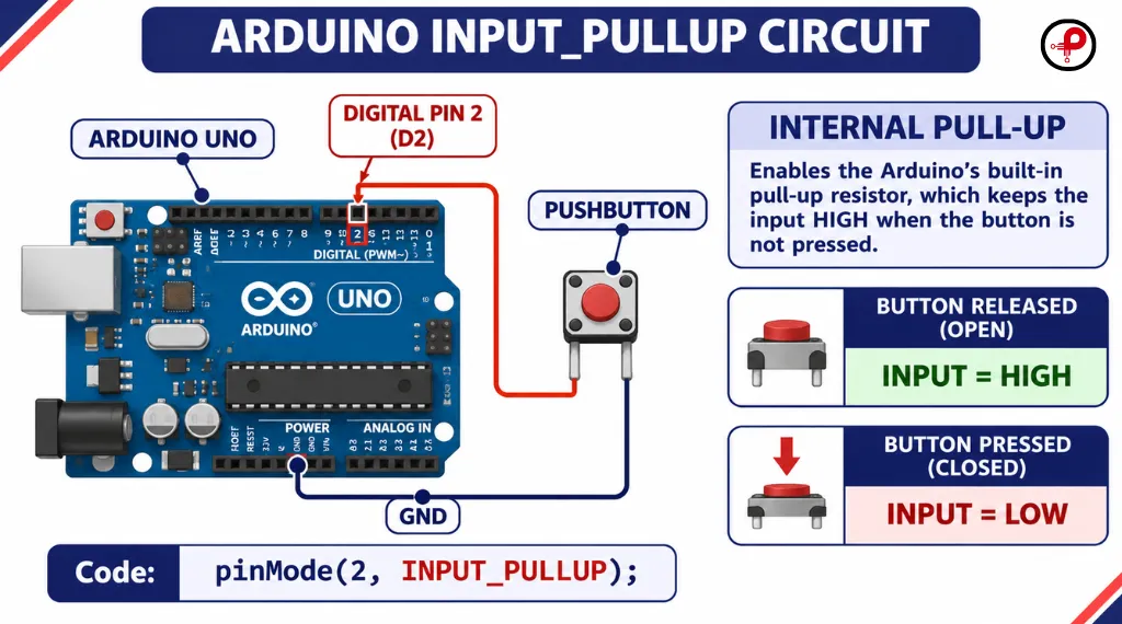
Arduino supports internal pull ups on boards and pins that provide this feature. For a simple example, connect one terminal of a pushbutton to digital pin 2 and the other terminal to GND.
The internal pull up keeps the input HIGH while the button is released.
const int buttonPin = 2;
const int ledPin = LED_BUILTIN;

void setup() {
  pinMode(buttonPin, INPUT_PULLUP);
  pinMode(ledPin, OUTPUT);
}

void loop() {
  bool pressed = digitalRead(buttonPin) == LOW;
  digitalWrite(ledPin, pressed ? HIGH : LOW);
}
When you press the button, the input reads LOW and the LED turns on. Release it, and the input returns HIGH. Notice the inverted logic. This is expected with INPUT_PULLUP.
The example follows Arduino’s documented behavior. The availability and electrical characteristics of internal pulls depend on the board’s microcontroller.
Mechanical buttons can also bounce as their contacts open and close. A pull up establishes the idle state, while debouncing is handled separately through software or a suitable hardware circuit.
Pull Up and Pull Down Resistors in STM32
STM32 microcontrollers provide GPIO configuration options for internal pull ups and pull downs. The available settings depend on the device family and pin.
In STM32CubeMX or STM32CubeIDE, select the GPIO pin and choose the required pull configuration. A button connected between the GPIO pin and ground can use an internal pull up. The input reads HIGH while released and LOW when pressed.
For an STM32 project using the traditional STM32 HAL interface, the configuration can look like this:
GPIO_InitTypeDef GPIO_InitStruct = {0};

__HAL_RCC_GPIOA_CLK_ENABLE();

GPIO_InitStruct.Pin = GPIO_PIN_0;
GPIO_InitStruct.Mode = GPIO_MODE_INPUT;
GPIO_InitStruct.Pull = GPIO_PULLUP;

HAL_GPIO_Init(GPIOA, &GPIO_InitStruct);
This example configures PA0 as an input with an internal pull up. It assumes the selected STM32 device supports that pin and configuration.
STM32 HAL versions and device families have different APIs. Check the package used by your project before copying the code. Newer HAL2 interfaces use different configuration types and names.
Why Does I²C Need Pull Up Resistors?
I²C is used by sensors, displays, EEPROMs and other peripheral devices. It communicates over two signal lines:
- SDA: Serial Data.
- SCL: Serial Clock.
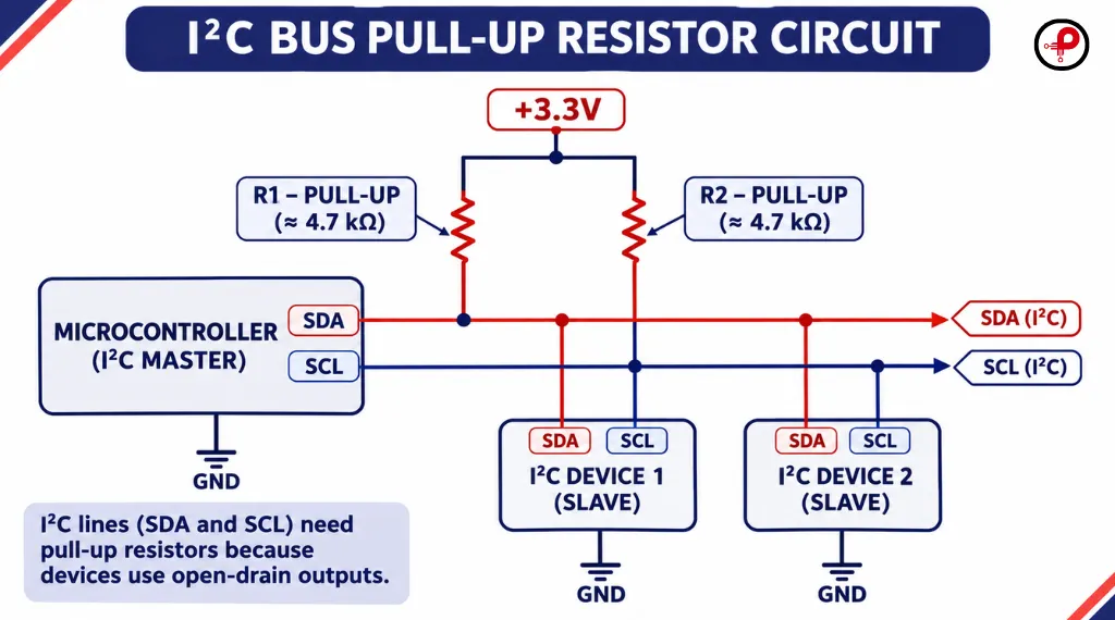
In a conventional I²C bus, devices use open-drain or open-collector outputs. A device can pull a line LOW, then release it. The pull up resistor brings the line back HIGH.
Each bus line needs an effective pull up to a suitable logic supply. Both SDA and SCL must meet the voltage and timing requirements of the connected devices. Our guide to the I²C communication protocol explains how I²C compares with SPI and UART, including the way these interfaces use their signal lines.
I²C Pull Up Resistor Calculation
I²C resistor selection has two electrical limits. The minimum resistance is set by the current a device must sink when it pulls the bus LOW.
The maximum resistance is set by bus capacitance and the permitted rise time:
Here, VCC is the pull up supply, VOL(max) is the maximum LOW voltage, IOL is the specified sink current, tr is the permitted rise time and Cb is the bus capacitance.
Texas Instruments explains both limits in its I²C pull up resistor calculation application report.
Worked Example: 3.3 V I²C Bus
Assume a design with a supply voltage of 3.3 V, maximum LOW voltage of 0.4 V, sink-current specification of 3 mA, bus capacitance of 200 pF and maximum rise time of 300 ns.
First, calculate the minimum resistance:
Now calculate the maximum resistance:
The calculated range is approximately 967 Ω to 1.77 kΩ. A standard 1.5 kΩ resistor falls within these limits, assuming the connected devices meet the stated voltage and sink-current specifications.
This example uses defined bus conditions. A different capacitance, supply or speed requirement will produce a different result.
What Happens When Several I²C Modules Have Pull Ups?
Many sensor and display breakout boards include their own pull up resistors. Connecting several boards to the same bus places those resistors in parallel.
For three identical 4.7 kΩ pull ups:
The bus now has an effective pull up resistance of about 1.57 kΩ. That changes the current when a device pulls the line LOW and affects the rising edge.
Check the combined resistance against the bus specifications before adding another pull up.
Open-Drain and Open-Collector Outputs
An open-drain MOSFET output can connect a signal to ground when its transistor turns on. When it turns off, the output becomes high impedance. The pull up resistor supplies the HIGH state after the transistor releases the line.
Open-collector outputs work on the same principle using a bipolar transistor. This arrangement allows multiple devices to share a signal line. I²C uses this type of wired signaling, and you will also find it on interrupt, fault and status outputs.
A push-pull output works differently. It actively drives the signal HIGH and LOW. External pull ups are usually unnecessary for ordinary push-pull logic, and connecting two push-pull outputs together can cause output contention.
Common Applications of Pull Up and Pull Down Resistors
Pushbuttons and switches: A pull resistor gives a GPIO a known reading while the button is released. This is one of the most common uses in Arduino and STM32 projects.
Microcontroller GPIO inputs: Configuration pins and external control signals may need a defined state when their source is disconnected or inactive.
Reset and enable pins: A pull resistor can hold a reset or enable input in its required idle state. Follow the device’s startup and reset specifications when wiring these pins.
I²C communication: Pull ups return SDA and SCL HIGH when devices release the bus.
Open-drain interrupt outputs: A pull up lets a shared interrupt line return HIGH after the device stops asserting it.
Transistor control inputs: A pull down can hold a MOSFET or other control input LOW while the driving circuit is inactive. The resistor must suit the device’s gate or input requirements.
Common Pull Up and Pull Down Resistor Mistakes
Leaving a GPIO Input Floating
An input without a defined voltage may produce random readings. Enable a suitable internal pull or connect an external resistor.
Choosing an Excessively High Resistance
A very large resistor may allow leakage current or interference to shift the input voltage. Check worst-case input leakage and logic thresholds.
Choosing an Excessively Low Resistance
A low value draws more current when the input is pulled to the opposite rail. Calculate the current and confirm that the switch or output device can handle it.
Pulling a Pin to the Wrong Supply Voltage
A 5 V pull up can damage a 3.3 V-only input. Check the GPIO voltage ratings and use a compatible supply or level-shifting circuit.
Assuming Every GPIO Has an Internal Pull Down
Internal pull options differ between devices and pins. Check the exact microcontroller datasheet and reference manual.
Ignoring Pull Ups Already Installed on I²C Modules
Several breakout boards may add parallel resistors. Calculate their combined value before installing more.
Confusing Pull Up Resistors With Debouncing
A pull up establishes the idle logic level. Mechanical contact bounce can still produce several quick transitions when a button is pressed. Handle that with software debouncing or a suitable hardware filter.
Troubleshooting a Pull Up or Pull Down Circuit
Start with a multimeter. Check the supply and ground connections, then measure the input while the switch is released.
A pull up input should read HIGH. A pull down input should read LOW. Press the switch and check that the voltage moves to the opposite state.
If it does not, inspect the resistor value, breadboard rows, jumper wires and button connections. Next, review the GPIO configuration. A pin accidentally configured as an output may behave very differently from a high-impedance input.
For an I²C problem, a multimeter may confirm the idle voltage, but it cannot show the shape of a rising edge. Use an oscilloscope to inspect SDA and SCL when communication fails at higher speeds or with longer wiring.
Pull Up Resistor FAQs
Is 10 kΩ a good pull up resistor value?
It is a common starting value for simple pushbutton inputs. Confirm that the input leakage, logic threshold, wiring capacitance and current requirements permit it.
What is the difference between a pull up and a pull down resistor?
A pull up connects the input to VCC and gives it a default HIGH state. A pull down connects it to ground and gives it a default LOW state.
Can I use an internal Arduino pull up resistor?
Yes. On supported Arduino boards, pinMode(pin, INPUT_PULLUP) enables the internal pull up. The button should connect the input pin to GND, so a press reads LOW.
Why does I²C require pull up resistors?
I²C devices release SDA and SCL when they want the bus HIGH. The pull up resistors return the lines to that state. Their values must meet the bus’s sink-current and rise-time limits.
Can multiple pull up resistors be connected to one line?
Yes. They combine in parallel, reducing the effective resistance. Calculate the combined value and check the current when the line is LOW.
Conclusion
Pull up and pull down resistors give digital inputs a defined state when an external device leaves the signal undriven. A 10 kΩ resistor is a useful starting point for many pushbutton circuits, while I²C and other faster signals require calculations based on current and timing limits.
Before choosing a value, check the microcontroller’s input thresholds, leakage current and voltage ratings. For an I²C bus, calculate both resistance limits and include any pull ups already fitted to the connected modules.
Technical References
- SparkFunPull Up Resistors Tutorial
- Arduino DocumentationINPUT, INPUT_PULLUP and OUTPUT
- Texas InstrumentsI²C Bus Pullup Resistor Calculation, SLVA689
- NXP SemiconductorsUM10204 I²C-bus Specification and User Manual
- STMicroelectronicsSTM32 HAL GPIO Documentation
- Build Electronic CircuitsPull Up Resistor Guide