




You have a Raspberry Pi, a few jumper wires, and a sensor ready to connect. Then you look at the GPIO header. Forty pins, two rows, and several labels that look almost identical.
That is where a pinout diagram comes in. It tells you which connection supplies power, which one provides ground, and which pins can communicate with external components. Get those connections right before switching on the board.
This guide covers the standard Raspberry Pi 40-pin GPIO header, physical and BCM numbering, communication interfaces, and practical wiring. It also explains the pinout differences between Raspberry Pi 4, Pi 5, Pi 3B+, Zero, Zero 2 W, 3A+, and Pico.
What Is a Raspberry Pi GPIO Pinout?
GPIO stands for General Purpose Input/Output. These pins let a Raspberry Pi exchange signals with external electronics, including LEDs, push buttons, sensors, displays, relay modules, and other circuit boards.
A pinout diagram identifies each connection and its function. It shows where to connect the power supply, ground, and signal wires.
Most Raspberry Pi computers have a 40-pin GPIO header. It consists of two rows of 20 pins. Depending on the pin, you can use it for:
- Power: 5V or 3.3V supply connections.
- Ground: A common electrical reference for connected circuits.
- Digital input and output: Reading switches or controlling external circuits.
- Communication: Interfaces such as I2C, SPI, and UART.
- Alternate functions: PWM, PCM, and other hardware features.
The Raspberry Pi Pico has a different pin arrangement because it uses the RP2040 microcontroller. Its pinout needs a separate reference.
The official Raspberry Pi computer hardware documentation provides additional details about the GPIO header and supported hardware.
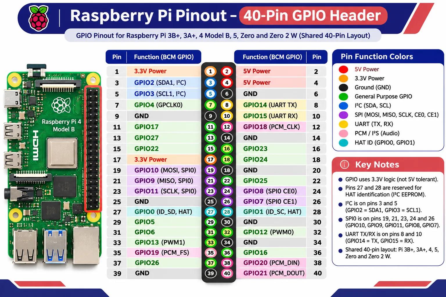
Raspberry Pi 40-Pin GPIO Pinout
The standard Raspberry Pi computer header contains 40 physical pins. Each position has a physical number, and most GPIO connections also have a Broadcom GPIO number, commonly called the BCM number.
The table below shows the standard arrangement found on Raspberry Pi 4, Raspberry Pi 5, Raspberry Pi 3B+, and Raspberry Pi Zero models with a 40-pin header.
Raspberry Pi 40-Pin GPIO Pinout Table
| Physical Pin | Pin Function | Physical Pin | Pin Function |
|---|---|---|---|
| 1 | 3.3V Power | 2 | 5V Power |
| 3 | GPIO2 / SDA1 | 4 | 5V Power |
| 5 | GPIO3 / SCL1 | 6 | Ground |
| 7 | GPIO4 | 8 | GPIO14 / TXD0 |
| 9 | Ground | 10 | GPIO15 / RXD0 |
| 11 | GPIO17 | 12 | GPIO18 / PCM_CLK |
| 13 | GPIO27 | 14 | Ground |
| 15 | GPIO22 | 16 | GPIO23 |
| 17 | 3.3V Power | 18 | GPIO24 |
| 19 | GPIO10 / SPI0_MOSI | 20 | Ground |
| 21 | GPIO9 / SPI0_MISO | 22 | GPIO25 |
| 23 | GPIO11 / SPI0_SCLK | 24 | GPIO8 / SPI0_CE0 |
| 25 | Ground | 26 | GPIO7 / SPI0_CE1 |
| 27 | GPIO0 / ID_SD | 28 | GPIO1 / ID_SC |
| 29 | GPIO5 | 30 | Ground |
| 31 | GPIO6 | 32 | GPIO12 |
| 33 | GPIO13 | 34 | Ground |
| 35 | GPIO19 / PCM_FS | 36 | GPIO16 |
| 37 | GPIO26 | 38 | GPIO20 / PCM_DIN |
| 39 | Ground | 40 | GPIO21 / PCM_DOUT |
Physical pin 1 sits at the corner of the header. Pin 2 is directly opposite it, and the numbering continues down both rows.
Check the board orientation before connecting anything. A pinout viewed from the wrong side can lead to a wiring mistake.
Physical Pin Numbering vs BCM Numbering
Raspberry Pi GPIO uses two numbering systems. You will encounter both when following wiring diagrams and writing Python programs.
Physical numbering identifies a pin by its position on the header. For example, physical pin 11 is the eleventh position in the numbering sequence.
BCM numbering identifies the GPIO connection by its Broadcom GPIO number. Physical pin 11 connects to GPIO17, so its BCM number is 17.
A few common mappings are shown below.
| Physical Pin | BCM Number | Function |
|---|---|---|
| 3 | GPIO2 | I2C SDA |
| 5 | GPIO3 | I2C SCL |
| 7 | GPIO4 | General GPIO |
| 8 | GPIO14 | UART TX |
| 10 | GPIO15 | UART RX |
| 11 | GPIO17 | General GPIO |
| 12 | GPIO18 | PWM / PCM |
| 13 | GPIO27 | General GPIO |
| 19 | GPIO10 | SPI MOSI |
| 21 | GPIO9 | SPI MISO |
| 23 | GPIO11 | SPI Clock |
Say a wiring tutorial asks you to connect an LED to GPIO17. On the physical header, that connection is pin 11.
The distinction matters in code too. GPIO Zero uses BCM numbering by default, so the following declaration refers to GPIO17:
led = LED(17)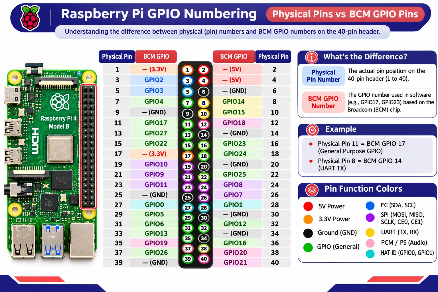
Raspberry Pi GPIO Pin Functions
Some header positions provide power or ground. Others work as digital inputs and outputs, while several support additional hardware functions.
Power Pins
The standard header provides two supply voltages.
- 5V: Physical pins 2 and 4.
- 3.3V: Physical pins 1 and 17.
The 5V connections can power compatible accessories. The 3.3V connections supply suitable low-voltage sensors and modules.
Check the current requirements of the device before connecting it. The available current depends on the Raspberry Pi model, its power supply, and the other loads connected to the board.
If you are choosing a supply for an electronics project, our guide to power supplies for embedded systems explains voltage regulation and current requirements.
Ground Pins
Ground provides the common electrical reference for the Raspberry Pi and connected components. It also completes the current path in a circuit.
The 40-pin header has eight ground connections:
- Physical pin 6
- Physical pin 9
- Physical pin 14
- Physical pin 20
- Physical pin 25
- Physical pin 30
- Physical pin 34
- Physical pin 39
For a sensor or display, connect its ground to a suitable Raspberry Pi ground pin. Follow the module’s wiring diagram, especially when an external power supply is involved.
General-Purpose Input/Output Pins
A GPIO pin can read a digital signal or control an external circuit.
Set a pin as an input and it can detect a HIGH or LOW signal from a push button, switch, or digital sensor. Configure it as an output and your program can set the pin HIGH or LOW.
For example, GPIO17 can control an LED through a suitable resistor. The same pin can also read a digital signal when configured as an input.
Raspberry Pi GPIO uses 3.3V logic. Never apply a 5V signal directly to a GPIO input.
Reserved ID Pins
Physical pins 27 and 28 connect to GPIO0 and GPIO1. They support the HAT identification interface, which allows compatible add-on boards to identify themselves.
Leave these connections available when using hardware that relies on HAT identification. They are usually excluded from ordinary beginner GPIO projects.
The header has 28 GPIO-related positions when these two ID connections are included. The remaining 26 are commonly available for general-purpose projects.
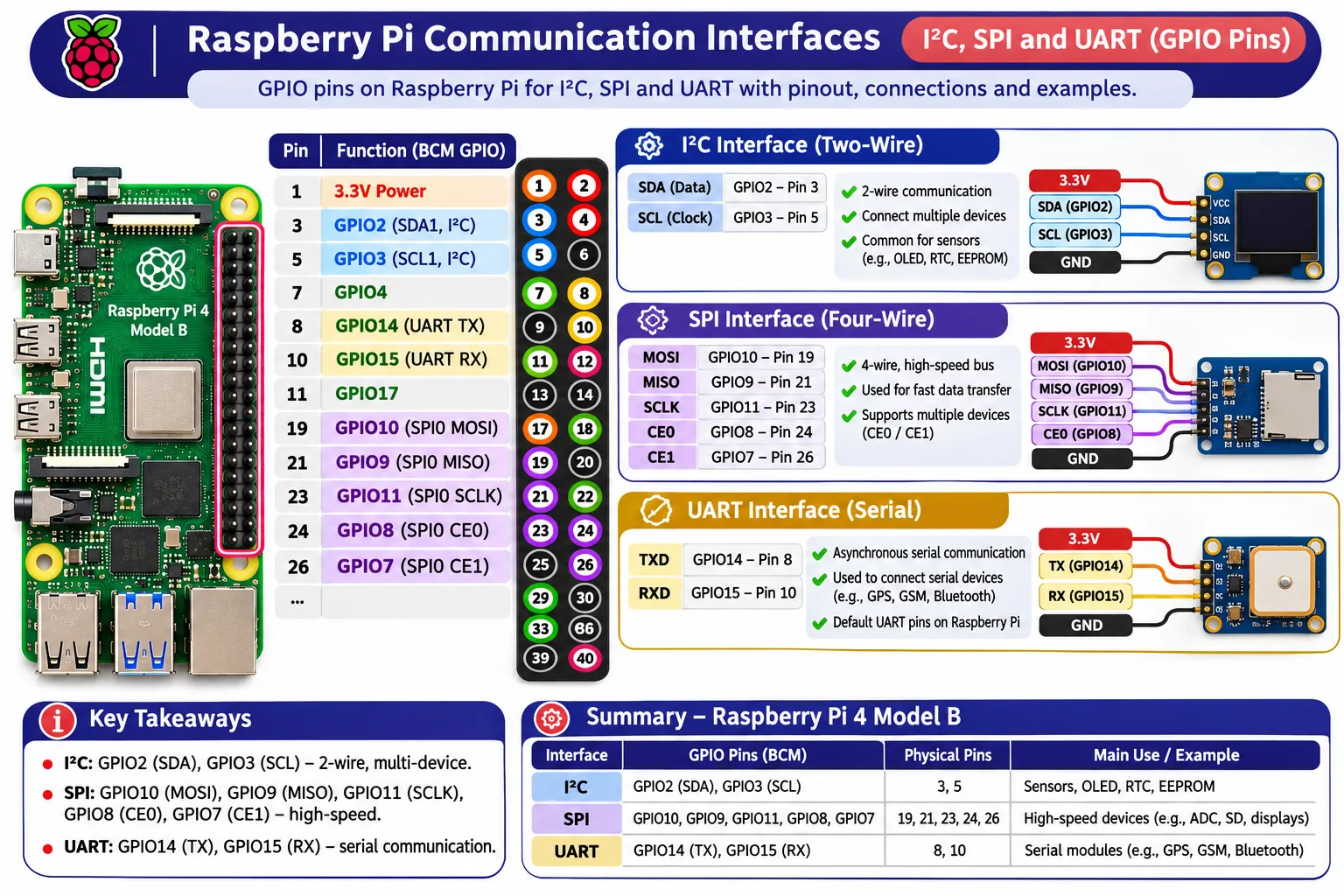
Raspberry Pi Communication Interfaces
Several GPIO pins have alternate functions that allow the Raspberry Pi to communicate with external devices. The same pin can serve different purposes, depending on the interface and configuration.
I2C Interface
I2C uses two signal lines to communicate with connected devices. You will find it on many temperature sensors, OLED displays, RTC modules, and I/O expanders.
The standard I2C1 connections are:
| Physical Pin | BCM Pin | Function |
|---|---|---|
| 3 | GPIO2 | SDA1 |
| 5 | GPIO3 | SCL1 |
SDA carries data, while SCL carries the clock signal. Multiple I2C devices can share the same bus if their addresses do not conflict.
For example, an OLED display and a temperature sensor can share SDA and SCL. Each device needs its own I2C address.
If you are choosing a communication interface for a project, read our comparison of I2C vs SPI vs UART.
SPI Interface
SPI is a synchronous communication protocol used by displays, ADCs, memory devices, and other peripherals. It has separate data lines for sending and receiving information, along with a clock and chip-select signals.
The standard SPI0 assignments are:
| Physical Pin | BCM Pin | SPI Function |
|---|---|---|
| 19 | GPIO10 | MOSI |
| 21 | GPIO9 | MISO |
| 23 | GPIO11 | SCLK |
| 24 | GPIO8 | CE0 |
| 26 | GPIO7 | CE1 |
MOSI carries data from the Raspberry Pi to a peripheral. MISO carries data in the opposite direction, and SCLK provides the clock signal.
CE0 and CE1 select the connected peripheral. Additional devices can use other chip-select arrangements when the hardware and software support them.
UART Interface
UART provides serial communication between the Raspberry Pi and another device. It is useful when connecting microcontrollers, GPS modules, serial adapters, or debugging equipment.
On Raspberry Pi models that expose the primary UART through the GPIO header, the familiar connections are:
| Physical Pin | BCM Pin | Function |
|---|---|---|
| 8 | GPIO14 | TX |
| 10 | GPIO15 | RX |
TX sends data, while RX receives it. Connect the transmitter of one device to the receiver of the other, and connect their grounds.
Raspberry Pi 5 needs special attention here. Its primary UART is exposed through a dedicated debug connector. GPIO14 and GPIO15 remain available for alternate functions, but the primary serial connection is handled differently.
Check the official Raspberry Pi configuration documentation before wiring a serial device.
PWM Pins
PWM stands for Pulse Width Modulation. It controls the average power delivered to a load by switching a signal on and off at a selected frequency.
You can use PWM to adjust LED brightness or send control signals to a compatible motor driver.
GPIO12, GPIO13, GPIO18, and GPIO19 are associated with PWM functions on supported Raspberry Pi models. The available channels and configuration depend on the board and software.
Software PWM is also possible through suitable libraries. Its timing can be affected by the operating system and other running processes.
For motor projects, use a suitable driver circuit. A GPIO pin cannot supply the current required by a motor.
PCM and I2S Audio Pins
The Raspberry Pi has pins associated with PCM digital audio communication. Compatible audio hardware can use these connections to transfer digital audio data.
| Physical Pin | BCM Pin | Function |
|---|---|---|
| 12 | GPIO18 | PCM_CLK |
| 35 | GPIO19 | PCM_FS |
| 38 | GPIO20 | PCM_DIN |
| 40 | GPIO21 | PCM_DOUT |
These signals are used by supported PCM and I2S-compatible hardware. Check the audio module’s documentation before connecting it.
Raspberry Pi GPIO Voltage and Safety
Raspberry Pi GPIO pins use 3.3V logic. They have electrical limits, and exceeding those limits can damage the board.
The GPIO pins are not 5V tolerant. A 5V signal connected directly to a GPIO input can cause permanent damage.
Before powering a circuit, check the following:
- Confirm the operating voltage of every connected module.
- Use a suitable logic-level converter for 5V signals.
- Add a transistor or driver circuit when controlling a relay, motor, or other higher-current load.
- Connect external circuit grounds when the interface requires a common reference.
- Check for short circuits between power and ground.
- Verify the pin numbering and board orientation.
A GPIO pin is meant to handle control signals. It should not power a motor or another high-current load directly.
The official Raspberry Pi documentation describes the GPIO hardware and its electrical limits.
Pull-up and pull-down resistors are also worth understanding when working with buttons and digital inputs. Our guide to pull-up resistors explains how they give an input a defined state when a switch is open.
Raspberry Pi Model-Specific Pinouts
Most Raspberry Pi computers share the standard 40-pin GPIO arrangement. The physical pin assignments remain familiar across these models, although their internal hardware and additional connectors differ.
The Pico is the exception. It uses a microcontroller and has its own pin layout.
Raspberry Pi 4 Pinout
The Raspberry Pi 4 Model B has a standard 40-pin GPIO header. Its pins provide power, ground, general-purpose input and output, and interfaces such as I2C, SPI, and UART.
Many wiring diagrams made for other standard-header Raspberry Pi computers will also work with the Pi 4. Check the board orientation and pin numbering before connecting a module.
The Raspberry Pi 4 specifications list its hardware features and connectors.
Raspberry Pi 5 Pinout
The Raspberry Pi 5 also has a standard 40-pin GPIO header. Its physical pin arrangement is familiar to anyone who has used a Raspberry Pi 4.
There is a hardware difference worth knowing. The Pi 5 uses the RP1 I/O controller to manage many of its peripheral connections. Software that accesses hardware directly may need changes when moved from an older model.
The Pi 5 also has a dedicated four-pin fan connector. It is separate from the GPIO header and intended for compatible cooling accessories.
The Raspberry Pi RP1 documentation describes the controller and its peripheral interfaces. The Raspberry Pi 5 product page lists the board’s connectors and hardware features.
Raspberry Pi 3B+ Pinout
The Raspberry Pi 3 Model B+ uses the standard 40-pin GPIO header. Its power, ground, and common communication pin assignments follow the familiar layout.
A GPIO diagram written for the Pi 4 can help with Pi 3B+ wiring too, provided it uses the standard header connections and the software supports the older board.
Raspberry Pi Zero Pinout
The Raspberry Pi Zero family follows the standard 40-pin GPIO arrangement. Some Zero boards are supplied without a pre-soldered header.
If your board has an unpopulated header, solder the required pins before connecting jumper wires or compatible HATs.
Its small size makes the Zero useful for compact electronics projects and lightweight embedded applications.
Raspberry Pi Zero 2 W Pinout
The Raspberry Pi Zero 2 W also follows the standard 40-pin GPIO layout. Its physical pin assignments match the familiar Raspberry Pi arrangement.
Check whether your particular board has a soldered header before planning the wiring. This is easy to overlook when ordering a bare board.
Raspberry Pi 3A+ Pinout
The Raspberry Pi 3A+ has the standard 40-pin GPIO header. Its smaller board layout differs from the 3B+ in other hardware features, but the main GPIO assignments remain familiar.
Use a standard Raspberry Pi GPIO reference to identify its physical pin positions and communication connections.
Raspberry Pi Pico Pinout
The Raspberry Pi Pico has a different pinout from Raspberry Pi computers. It uses the RP2040 microcontroller and provides 40 edge connections, including 26 multifunction GPIO pins.
The Pico supports ADC inputs, PWM, I2C, SPI, and UART. Its pin functions and numbering must be checked against the Pico pinout diagram.
There is one useful difference for sensor projects. Standard Raspberry Pi computers do not have built-in analog GPIO inputs, while the Pico provides accessible ADC channels.
Do not use a Raspberry Pi 4 or Pi 5 GPIO diagram when wiring a Pico. The board layout and pin assignments are different.
The official Raspberry Pi Pico documentation includes board layouts and hardware details. The Pico datasheet provides the pin and electrical specifications.
If you are comparing microcontroller boards, our guides to the Arduino Nano pinout and Arduino Uno pinout show how their connections differ.
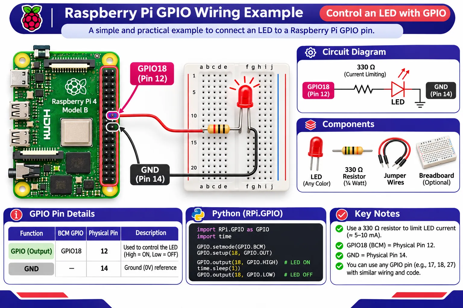
Practical Raspberry Pi GPIO Wiring Example
An LED is a useful first GPIO project. You can wire it to one output pin and use a short Python program to switch it on and off.
For this example, use GPIO17, which is physical pin 11. Connect the LED in series with a suitable current-limiting resistor.
LED Wiring Connections
| Raspberry Pi Connection | LED Circuit |
|---|---|
| Physical pin 11 / GPIO17 | Resistor and LED connection |
| Ground pin | LED return path |
| Series resistor | Limits current through the LED |
Check the LED polarity before connecting the circuit. Its anode is the positive side, and its cathode is the negative side. The resistor can sit on either side of the LED as long as it remains in series.
Python Code to Blink an LED
The GPIO Zero library makes basic LED control straightforward. Its documentation includes examples for LEDs, buttons, sensors, and other devices.
from gpiozero import LED
from time import sleep

led = LED(17)

while True:
    led.on()
    sleep(1)

    led.off()
    sleep(1)
The program sets GPIO17 HIGH, waits one second, and switches it LOW. The loop repeats until you stop the program.
Notice the number in LED(17). GPIO Zero uses BCM numbering by default, so the code refers to GPIO17 rather than physical pin 11.
The GPIO Zero documentation has more examples if you want to try a push button or another component next.
Other Projects You Can Build with Raspberry Pi GPIO
Once you know the pin assignments, you can start connecting sensors and modules.
Temperature sensors: A digital temperature sensor can send readings through I2C or another supported digital interface. Our ESP32 sensor and module guides cover common sensor connections and interface concepts used in embedded projects.
OLED displays: Small OLED screens can show sensor readings, system information, and project status. Many use I2C, which means they share SDA and SCL connections with other devices on the same bus.
Relay modules: A compatible relay module can switch an external circuit using a GPIO control signal. Use the correct driver and isolation arrangement. Never connect a bare relay coil directly to a GPIO pin.
Push buttons: A button can provide a digital input. Configure a suitable pull-up or pull-down resistor so the input has a defined state when the button is released.
Motor drivers: A motor driver receives control signals from the Raspberry Pi and supplies the current required by the motor. Use a suitable external power source for the motor.
How to Check the Raspberry Pi Pinout from the Terminal
You can also check GPIO information from the Raspberry Pi itself. On supported Raspberry Pi OS installations, open a terminal and run:
pinoutThe command displays a pinout reference for the detected board. It is handy when you are working at the bench and need to check a connection without opening another diagram.
If the command is unavailable on your installation, check the Raspberry Pi OS documentation and available packages for your system.
Common Raspberry Pi GPIO Wiring Mistakes
A circuit may fail because of one misplaced jumper wire or an incorrect pin number. Check these points when a project refuses to work.
Using the wrong numbering system: Your wiring diagram may show physical pin numbers while your Python program uses BCM numbers. Confirm the mapping before running the code.
Connecting 5V to a GPIO input: GPIO uses 3.3V logic. A 5V signal needs a suitable level shifter before it reaches the input.
Forgetting ground: External modules that communicate through GPIO usually need a common ground reference with the Raspberry Pi.
Reversing LED polarity: An LED connected in the wrong direction will not light. Check its anode and cathode.
Leaving out the current-limiting resistor: An LED needs a suitable resistor to keep its current within safe limits.
Powering a motor from a GPIO pin: GPIO pins cannot provide the current a motor needs. Use a motor driver and an appropriate external supply.
Using the wrong board diagram: The Pico has a different pinout from standard Raspberry Pi computers. Check the exact model before wiring.
Raspberry Pi Pinout FAQs
What is the Raspberry Pi GPIO pinout?
The Raspberry Pi GPIO pinout identifies the function of each connection on the board’s GPIO header. It shows physical pin numbers, GPIO numbers, power and ground connections, and communication functions.
How many GPIO pins does a Raspberry Pi have?
A standard Raspberry Pi computer header has 40 physical positions. These include power, ground, and GPIO-related connections. Two positions are reserved for HAT identification, leaving 26 pins commonly available for general projects.
What is the Raspberry Pi 4 pinout?
The Raspberry Pi 4 Model B uses a standard 40-pin GPIO header. It includes 5V, 3.3V, ground, and GPIO connections with support for I2C, SPI, UART, PWM, and other functions.
Is the Raspberry Pi 5 pinout the same as the Raspberry Pi 4?
The Raspberry Pi 5 uses the same standard 40-pin physical GPIO layout as the Raspberry Pi 4. Its internal I/O architecture differs, so software that accesses hardware directly may need changes.
What is the Raspberry Pi Pico pinout?
The Raspberry Pi Pico uses a separate 40-connection layout based on the RP2040 microcontroller. It provides 26 multifunction GPIO pins, ADC inputs, PWM, and communication interfaces such as I2C, SPI, and UART.
Does the Raspberry Pi Zero have a 40-pin GPIO header?
The Raspberry Pi Zero family supports the standard 40-pin GPIO layout. Some versions are supplied without a soldered header, so you may need to install one before connecting external hardware.
What is the Raspberry Pi Zero 2 W pinout?
The Raspberry Pi Zero 2 W follows the standard 40-pin Raspberry Pi GPIO arrangement. Its physical pin assignments match the common reference used by other standard-header models.
Does the Raspberry Pi 3B+ use the same GPIO pinout?
Yes. The Raspberry Pi 3 Model B+ uses the standard 40-pin GPIO layout. Its common power, ground, I2C, SPI, and UART pin assignments follow the familiar header arrangement.
What is the Raspberry Pi 3A+ pinout?
The Raspberry Pi 3A+ has the standard 40-pin GPIO header. A standard Raspberry Pi GPIO reference can identify its physical pin positions and common interface connections.
Which pins are used for I2C on Raspberry Pi?
The standard I2C1 interface uses physical pin 3 for SDA1, connected to GPIO2, and physical pin 5 for SCL1, connected to GPIO3.
Which pins are used for SPI on Raspberry Pi?
The standard SPI0 interface uses GPIO10 for MOSI, GPIO9 for MISO, and GPIO11 for SCLK. Physical pins 24 and 26 provide CE0 and CE1 chip-select signals.
Which Raspberry Pi pins are used for UART communication?
On many Raspberry Pi models, physical pin 8 provides UART transmit through GPIO14, and physical pin 10 provides UART receive through GPIO15. Raspberry Pi 5 exposes its primary UART through a dedicated debug connector.
Are Raspberry Pi GPIO pins 5V tolerant?
No. Raspberry Pi GPIO pins use 3.3V logic and are not 5V tolerant. Use a suitable logic-level converter when connecting a device that sends 5V signals.
Can Raspberry Pi GPIO read analog signals?
Standard Raspberry Pi computers do not have built-in analog GPIO inputs. You can add an external ADC module to read analog signals. The Raspberry Pi Pico has built-in ADC inputs.
Does the Raspberry Pi 4 have a dedicated fan connector?
The Raspberry Pi 4 does not have the dedicated four-pin fan connector found on the Raspberry Pi 5. A compatible fan can be controlled through suitable GPIO wiring or an appropriate accessory.
Conclusion
When you are wiring a Raspberry Pi project, the physical pin number and the BCM number need to agree with your diagram and code. Check the voltage too, especially when connecting a module designed for 5V operation.
For the first test, keep the circuit simple. An LED on GPIO17 is enough to check the wiring and get your Python code running before you move on to sensors, displays, or other hardware.