

The Arduino Nano pinout is a familiar sight on electronics workbenches. It fits into a standard breadboard, runs many of the same sketches as the Arduino Uno and provides enough I/O connections for a wide range of small hardware projects.
Its pin arrangement deserves a closer look before you start wiring components. Some pins have more than one function, and choosing the wrong connection can cause problems when you combine sensors, displays and communication modules. D11, for example, works as a PWM output and also carries the SPI MOSI signal. A4 and A5 are used for analog measurements as well as I2C communication.
This guide covers the classic Arduino Nano based on the ATmega328P. We will examine its complete pinout, electrical specifications, communication interfaces and power connections. You will also find practical circuits, Arduino code examples, troubleshooting advice and PCB design considerations.
The goal is to help you understand the board well enough to wire up a circuit, test it and eventually move the design onto a custom PCB.
What Is an Arduino Nano?
The Arduino Nano is a small development board built for microcontroller-based electronics projects. It has two rows of header connections that fit into a breadboard, so you can assemble and test a circuit without designing a PCB first.
The classic version uses the ATmega328P, an 8-bit AVR microcontroller. This chip handles the digital inputs and outputs, analog measurements, timers, interrupts and serial communication used by the board.
The Nano also includes an onboard voltage regulator, a reset button and a USB-to-serial interface. A Mini-B USB connector provides a connection for programming and USB power.
You will find this board in sensor interfaces, small automation controllers, robotics experiments, data loggers and display-based projects. Its 5V logic is particularly useful when working with traditional Arduino-compatible modules.
Classic Arduino Nano Specifications
Here are the main specifications of the official classic Nano, product A000005.
| Parameter | Specification |
|---|---|
| Microcontroller | ATmega328P |
| Architecture | 8-bit AVR |
| Operating voltage | 5V |
| Clock speed | 16 MHz |
| Flash memory | 32 KB, including 2 KB used by the bootloader |
| SRAM | 2 KB |
| EEPROM | 1 KB |
| Dedicated digital I/O pins | 14 |
| Analog input channels | 8 |
| PWM outputs | 6 |
| ADC resolution | 10-bit |
| Communication interfaces | UART, I2C, SPI |
| USB connector | Mini-B USB |
| Recommended VIN input | 7 to 12V |
| Recommended maximum current per I/O pin | 20 mA |
| 3.3V output current limit | 50 mA |
| Nominal board dimensions | 45 × 18 mm |
| Weight | Approximately 7 g |
The 32 KB Flash figure includes the bootloader allocation. It should not be treated as 32 KB of space available for a sketch.
Arduino specifies 20 mA per I/O pin as the current limit for normal design. The ATmega328P datasheet gives a higher absolute maximum rating of 40 mA per pin, but that is a stress limit and should never be used as a routine operating target.
Arduino Nano vs Arduino Uno
The Nano and Uno R3 share the ATmega328P processor, so many sketches and libraries work on both boards without changes. The physical layout is where you notice the main differences.
| Feature | Arduino Nano | Arduino Uno R3 |
|---|---|---|
| Microcontroller | ATmega328P | ATmega328P |
| Clock speed | 16 MHz | 16 MHz |
| Operating voltage | 5V | 5V |
| Flash memory | 32 KB | 32 KB |
| SRAM | 2 KB | 2 KB |
| EEPROM | 1 KB | 1 KB |
| Digital I/O pins | 14 | 14 |
| Analog inputs | 8 | 6 |
| PWM pins | 6 | 6 |
| USB connector | Mini-B | USB-B |
| DC barrel jack | No | Yes |
| Nominal dimensions | 45 × 18 mm | 68.6 × 53.4 mm |
For a breadboard prototype or a compact enclosure, the Nano is easy to work with. The Uno R3 has a larger layout, a DC power jack and more room around its connectors.
One difference worth remembering is the analog input count. The Nano exposes A6 and A7 in addition to A0 to A5. Our Arduino Uno pinout guide covers the Uno’s layout in detail.
Arduino Nano Pinout Diagram
The classic Nano has 30 header positions arranged in two parallel rows. The connections cover digital I/O, analog inputs, power, reset and communication.
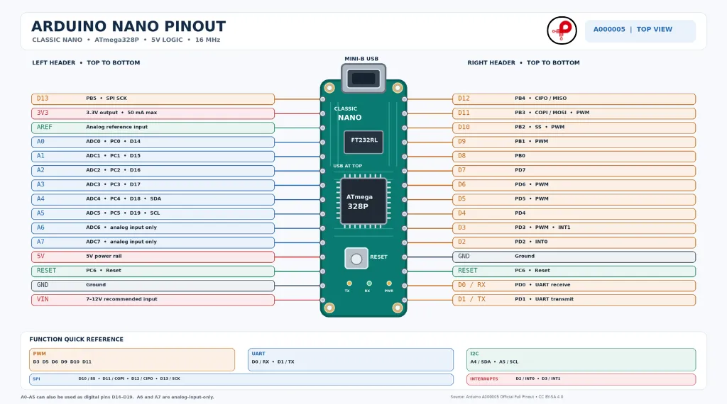
The board’s pins can be grouped by their functions.
| Pin group | Nano pins | Purpose |
|---|---|---|
| Digital I/O | D0 to D13 | Digital input and output |
| Analog inputs | A0 to A7 | Analog voltage measurement |
| PWM | D3, D5, D6, D9, D10, D11 | Duty-cycle control |
| UART | D0, D1 | Serial communication |
| I2C | A4, A5 | Two-wire communication |
| SPI | D10 to D13 | Synchronous serial communication |
| External interrupts | D2, D3 | Event-driven input |
| Power | VIN, 5V, 3V3, GND | Board and peripheral power |
| Control | RESET, AREF | Reset and analog reference |
Some connections appear in multiple groups because the ATmega328P shares hardware functions with its GPIO pins.
For example, D10 can operate as a normal digital output, but it also acts as the SPI slave-select connection. The circuit and software determine which function you use.
Arduino Nano Pin Functions Explained
Digital I/O Pins (D0 to D13)
The 14 digital pins can be configured as inputs or outputs using the Arduino functions pinMode(), digitalRead() and digitalWrite().
An input can read a push button or the output of a digital sensor. An output can control an LED or send a logic signal to a transistor driver.
On the classic 5V Nano, a HIGH output is approximately 5V and a LOW output is approximately 0V, measured relative to GND.
| Pin | Main function | Alternate function |
|---|---|---|
| D0 | Digital I/O | UART RX |
| D1 | Digital I/O | UART TX |
| D2 | Digital I/O | External interrupt INT0 |
| D3 | Digital I/O | PWM, external interrupt INT1 |
| D4 | Digital I/O | General-purpose I/O |
| D5 | Digital I/O | PWM |
| D6 | Digital I/O | PWM |
| D7 | Digital I/O | General-purpose I/O |
| D8 | Digital I/O | General-purpose I/O |
| D9 | Digital I/O | PWM |
| D10 | Digital I/O | PWM, SPI SS |
| D11 | Digital I/O | PWM, SPI MOSI |
| D12 | Digital I/O | SPI MISO |
| D13 | Digital I/O | SPI SCK, onboard LED |
The first two pins deserve attention when you are uploading sketches. D0 and D1 connect to the hardware UART, which is also used by the USB-to-serial interface. An external module connected to these lines can interfere with programming or Serial Monitor communication.
D13 has another detail. The onboard LED is connected to this pin, so its electrical behavior is affected by the LED circuit as well.
Pins D2 and D3 are useful for applications that need hardware interrupts. A rotary encoder or pulse counter is a common example.
A0 to A5 can also function as digital GPIO. On the classic Nano, these correspond to digital pin numbers D14 to D19. A6 and A7 do not have the same capability.
Practical example: Push button input
Connect one side of a push button to D2 and the other side to GND. The internal pull-up resistor keeps the input HIGH when the button is released.
const int buttonPin = 2;

void setup() {
  pinMode(buttonPin, INPUT_PULLUP);
  Serial.begin(9600);
}

void loop() {
  if (digitalRead(buttonPin) == LOW) {
    Serial.println("Button pressed");
  }

  delay(50);
}
When you press the button, D2 reads LOW. This arrangement saves you from adding an external pull-up resistor for a simple button circuit. Read our guide to pull up resistors for how this works.
Analog Input Pins (A0 to A7)
Analog inputs are used when the voltage from a sensor changes across a range. A potentiometer, an analog temperature sensor and an LDR voltage divider are common examples.
The ATmega328P includes a 10-bit ADC. With the default 5V analog reference, the conversion produces a value from 0 to 1023.
| Pin | ADC channel | Other function |
|---|---|---|
| A0 | ADC0 | Digital GPIO |
| A1 | ADC1 | Digital GPIO |
| A2 | ADC2 | Digital GPIO |
| A3 | ADC3 | Digital GPIO |
| A4 | ADC4 | Digital GPIO, SDA |
| A5 | ADC5 | Digital GPIO, SCL |
| A6 | ADC6 | Analog input only |
| A7 | ADC7 | Analog input only |
A6 and A7 are useful when the circuit needs extra analog channels. They cannot be configured as ordinary digital inputs or outputs.
How the ADC reading relates to voltage
With a 5V reference, the ADC has 1024 possible output codes. Each step represents roughly 4.9 mV.
For a simple voltage calculation, you can use:
This assumes the input stays within the ADC’s permitted range and that the reference voltage is known. The supply may not be exactly 5.000V, so use a measured reference value when accuracy matters.
Reading a potentiometer on A0
A 10 kΩ potentiometer makes a good test source. Connect the outer terminals to 5V and GND, then connect the middle terminal to A0.
const int sensorPin = A0;

void setup() {
  Serial.begin(9600);
}

void loop() {
  int rawValue = analogRead(sensorPin);

  float voltage = rawValue * (5.0 / 1023.0);

  Serial.print("ADC reading: ");
  Serial.print(rawValue);

  Serial.print(" | Voltage: ");
  Serial.println(voltage, 3);

  delay(300);
}
Turn the potentiometer while watching the Serial Monitor. The reading should move between values close to 0 and 1023.
The voltage calculation assumes a 5.0V reference. Measure the actual reference when you need better results. To measure voltages above 5V, scale them down first with our voltage divider calculator.
PWM Pins and Their Functions
The classic Nano supports PWM on six digital pins: D3, D5, D6, D9, D10 and D11.
PWM stands for Pulse Width Modulation. The microcontroller produces a repeating digital waveform and changes the amount of time the signal remains HIGH during each cycle.
This is useful for dimming LEDs or controlling the input of a compatible motor driver.
| Pin | Hardware timer | Default PWM frequency |
|---|---|---|
| D3 | Timer2 | Approximately 490 Hz |
| D5 | Timer0 | Approximately 980 Hz |
| D6 | Timer0 | Approximately 980 Hz |
| D9 | Timer1 | Approximately 490 Hz |
| D10 | Timer1 | Approximately 490 Hz |
| D11 | Timer2 | Approximately 490 Hz |
These are the standard frequencies for the classic Arduino Nano core. Changing timer registers or using certain libraries can alter PWM operation. For example, the Servo library uses Timer1 on the ATmega328P, which affects PWM availability on D9 and D10.
The analogWrite() function accepts a value between 0 and 255 on the classic Nano.
analogWrite() value | Approximate duty cycle |
|---|---|
| 0 | 0% |
| 64 | 25% |
| 128 | 50% |
| 192 | 75% |
| 255 | 100% |
LED brightness control using D9
Connect an LED in series with a 220 Ω or 330 Ω resistor between D9 and GND.
const int ledPin = 9;

void setup() {
  pinMode(ledPin, OUTPUT);
}

void loop() {
  for (int brightness = 0; brightness <= 255; brightness++) {
    analogWrite(ledPin, brightness);
    delay(10);
  }

  for (int brightness = 255; brightness >= 0; brightness--) {
    analogWrite(ledPin, brightness);
    delay(10);
  }
}
The LED gradually brightens and dims. An oscilloscope will show the changing duty cycle at D9.
PWM does not create a steady analog voltage. The output remains a digital waveform, so use a suitable filter or driver circuit when the application requires a smoother signal.
UART Communication Pins (D0 and D1)
UART is a serial communication interface used to exchange data between two devices without a shared clock signal.
The classic Nano exposes its hardware UART through D0 and D1.
| Pin | Signal | Direction |
|---|---|---|
| D0 | RX | Receives data |
| D1 | TX | Transmits data |
GPS receivers, serial Bluetooth modules and other microcontrollers commonly use UART.
When connecting two devices, cross the data connections. TX on the first device goes to RX on the Nano, while RX on the first device connects to D1. Both devices need a shared ground reference for a normal non-isolated connection.
The classic Nano uses 5V logic. A 3.3V peripheral may need a level shifter on signals entering it, depending on the peripheral’s input tolerance.
Sending a serial message
void setup() {
  Serial.begin(9600);
}

void loop() {
  Serial.println("Hello from Arduino Nano");
  delay(1000);
}
Set the Serial Monitor to 9600 baud to read the message.
One practical warning: D0 and D1 also connect to the board’s USB-to-serial interface. Disconnect external UART hardware when it prevents sketch uploads or produces unexpected serial data.
I2C Communication Pins (A4 and A5)
I2C uses two shared signal lines to communicate with compatible peripherals. SDA carries the data and SCL carries the clock.
On the classic Nano, A4 is SDA and A5 is SCL.
| Nano pin | I2C signal |
|---|---|
| A4 | SDA |
| A5 | SCL |
OLED displays, RTC modules, temperature sensors and accelerometers commonly use this interface.
Connecting an I2C OLED
| Display pin | Arduino Nano |
|---|---|
| VCC | According to the module specification |
| GND | GND |
| SDA | A4 |
| SCL | A5 |
Check the display’s logic voltage before connecting it. Some modules accept a 5V supply but use 3.3V logic internally. Others require 3.3V power as well.
I2C also needs pull-up resistors on SDA and SCL. Many breakout boards include them. When several breakout boards are connected, their resistors are placed in parallel, which can make the total pull-up resistance too low.
Finding I2C device addresses
An address conflict can prevent a display or sensor from responding correctly, even with accurate wiring. This scanner checks the bus and prints the addresses of responding devices.
#include <Wire.h>

void setup() {
  Wire.begin();
  Serial.begin(9600);

  Serial.println("I2C Scanner");
}

void loop() {
  byte deviceCount = 0;

  for (byte address = 1; address < 127; address++) {
    Wire.beginTransmission(address);
    byte error = Wire.endTransmission();

    if (error == 0) {
      Serial.print("Device found at 0x");

      if (address < 16) {
        Serial.print("0");
      }

      Serial.println(address, HEX);
      deviceCount++;
    }
  }

  if (deviceCount == 0) {
    Serial.println("No I2C devices found");
  }

  delay(3000);
}
Connect the module, upload the sketch and open the Serial Monitor. A detected device will appear with its hexadecimal address.
SPI Communication Pins (D10 to D13)
SPI is a synchronous serial interface that uses separate data lines for sending and receiving information. It is common in SD card modules, TFT displays and external memory devices.
The classic Nano uses four SPI connections.
| Nano pin | SPI signal | Function |
|---|---|---|
| D10 | SS | Slave Select |
| D11 | MOSI / COPI | Controller-to-peripheral data |
| D12 | MISO / CIPO | Peripheral-to-controller data |
| D13 | SCK | Serial clock |
MOSI and MISO are the traditional names. COPI and CIPO describe the same signal directions using newer terminology.
When several SPI peripherals share a bus, they can use the same MOSI, MISO and SCK connections. Each device normally has its own chip-select line.
D10 is the classic Nano’s hardware SS pin. When using the Nano as the SPI controller, configure D10 as an output to keep the controller in master mode. Individual peripherals can use separate chip-select outputs as required by their wiring.
Typical SPI wiring
| SPI module | Nano connection |
|---|---|
| MOSI | D11 |
| MISO | D12 |
| SCK | D13 |
| CS | D10 |
| GND | GND |
| VCC | As specified by the module |
Before connecting an SPI device, check its signal voltage. A 3.3V memory module may need level shifting when connected to the 5V Nano.
External Interrupt Pins
The ATmega328P has two dedicated external interrupt inputs on the classic Nano.
| Arduino pin | Interrupt |
|---|---|
| D2 | INT0 |
| D3 | INT1 |
An external interrupt allows the microcontroller to respond to a signal change without constantly checking the pin inside the main loop.
A rotary encoder, pulse sensor or tachometer can use these inputs to detect events. Supported trigger modes include LOW, CHANGE, RISING and FALLING.
Keep the interrupt service routine short. Avoid delay(), lengthy calculations and serial printing inside it. Set a flag or update a counter, then handle the remaining work in the main loop.
Power, Reset and AREF Pins
The power connections need just as much attention as the signal pins. A wrong connection here can damage the board before the sketch even starts.
| Pin | Purpose |
|---|---|
| VIN | External unregulated power input |
| 5V | 5V power rail |
| 3V3 | Regulated 3.3V output |
| GND | Ground reference |
| RESET | Microcontroller reset |
| AREF | External analog reference |
VIN accepts an external supply through the onboard voltage regulator. Arduino lists 7 to 12V as the recommended input range.
5V connects to the board’s 5V rail. A stable, regulated 5V source can power the board through this connection, but this bypasses the VIN regulator. The supply must be correctly regulated and checked against the exact board’s power circuit.
3V3 provides a regulated output for compatible peripherals. The official classic Nano pinout specifies a maximum of 50 mA from this connection. Keep the combined load within that limit.
GND provides the common voltage reference. Sensors and external modules that exchange signals with the Nano normally need a shared ground.
RESET restarts the microcontroller when pulled LOW. The USB-to-serial interface also uses the reset circuit during sketch uploading.
AREF allows an external voltage reference to be used by the ADC. Configure the board with analogReference(EXTERNAL) before taking measurements with an external reference. Never apply an external reference while the default reference is active, and keep the voltage within the ATmega328P’s permitted range.
How to Power an Arduino Nano
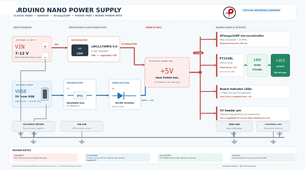
The classic Nano can run from USB, VIN or a regulated 5V supply connected to its 5V rail. Each method has different requirements.
USB Power
USB is convenient during programming and bench testing. Connect the Mini-B cable to a computer or a suitable 5V USB power source.
The USB connection supplies power and carries serial data for uploading sketches and using the Serial Monitor.
The original classic Nano uses an FTDI USB-to-serial chip. Many compatible boards use different chips, including CH340 variants, so a clone may need a different USB driver.
VIN Power Input
VIN is intended for an external DC supply. The recommended input range is 7 to 12V for the official classic Nano.
The onboard linear regulator reduces the supply to the 5V rail. Since it is a linear regulator, the voltage difference is dissipated as heat.
Consider an illustrative 12V input with a 100 mA load from the 5V regulator:
That is 0.7W of regulator dissipation, which can produce substantial heating on a small board. The actual result depends on the regulator, board layout and load.
If your project has a relay, motor or other high-current peripheral, give it an appropriate driver and power supply rather than drawing its load current through the Nano’s regulator. Our guide to power supplies for embedded systems helps you choose one.
Regulated 5V Input
A properly regulated 5V source can be connected to the Nano’s 5V rail. This avoids the voltage drop across the VIN linear regulator.
Measure the supply before connecting it. An incorrect voltage on the 5V rail can reach the ATmega328P directly.
Also check the board schematic before using USB and an external 5V supply at the same time. Original boards and clones can have different power-selection arrangements.
Common Arduino Nano Power Mistakes
| Mistake | Possible result | How to prevent it |
|---|---|---|
| Connecting 12V to the 5V pin | Damage to the board | Use VIN or a properly regulated 5V supply |
| Applying excessive voltage to VIN | Regulator overheating or damage | Follow the recommended VIN range |
| Driving a motor directly from GPIO | Damaged output pin | Use a motor driver |
| Overloading the 3.3V output | Regulator overload | Add a separate suitable 3.3V regulator |
| Leaving the grounds disconnected | Unreliable signal readings | Connect grounds as required |
| Connecting 5V signals to a 3.3V-only module | Peripheral damage | Use a suitable logic-level shifter |
A relay module with a built-in driver is convenient for low-voltage control projects. A bare relay coil needs its own transistor or MOSFET driver and flyback protection.
Arduino Nano Practical Wiring Examples
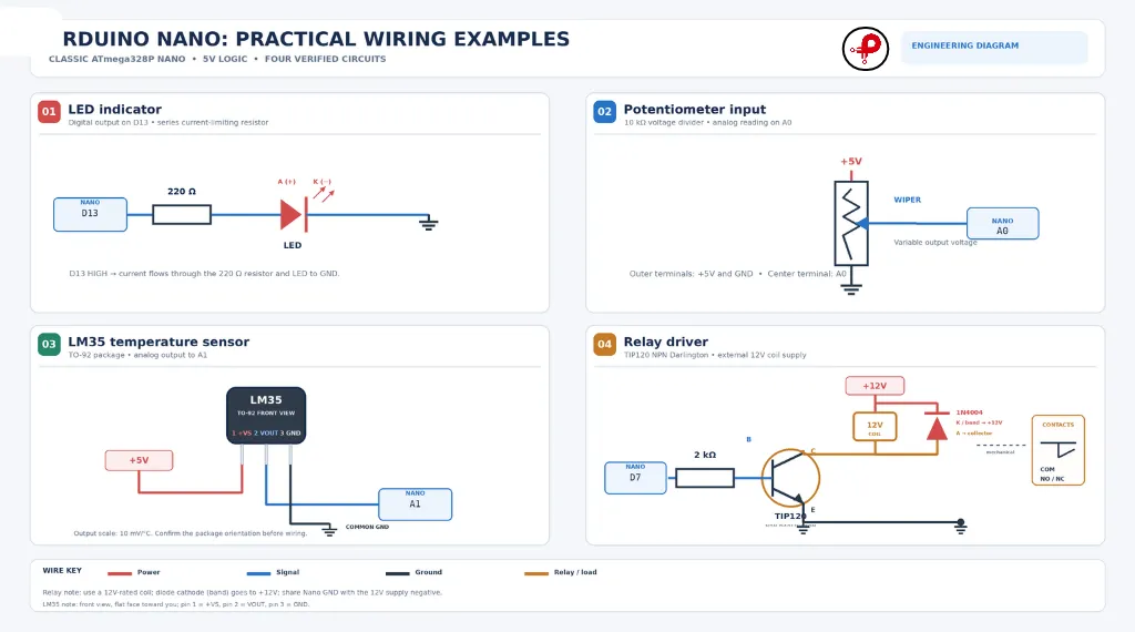
The pinout makes more sense when you use it in a working circuit. These examples start with simple components and move towards communication modules.
Connecting an LED
Connect the LED anode to D13 through a 220 Ω or 330 Ω resistor. Connect its cathode to GND.
const int ledPin = 13;

void setup() {
  pinMode(ledPin, OUTPUT);
}

void loop() {
  digitalWrite(ledPin, HIGH);
  delay(1000);

  digitalWrite(ledPin, LOW);
  delay(1000);
}
The LED stays ON for one second and OFF for one second. Since D13 also connects to the onboard LED, you can run this example without adding an external LED.
Connecting a Potentiometer
Use a 10 kΩ potentiometer to test A0.
| Potentiometer terminal | Nano connection |
|---|---|
| Outer terminal 1 | 5V |
| Center terminal | A0 |
| Outer terminal 2 | GND |
The following sketch reads the input and displays its value.
const int potPin = A0;

void setup() {
  Serial.begin(9600);
}

void loop() {
  int value = analogRead(potPin);

  Serial.print("ADC value: ");
  Serial.println(value);

  delay(200);
}
Rotate the shaft while watching the Serial Monitor. The value should change across the available ADC range.
Connecting an Analog Temperature Sensor
A compatible analog sensor can connect to A0, provided its output voltage stays within the ADC input range.
| Sensor connection | Nano connection |
|---|---|
| VCC | Supply specified by sensor |
| GND | GND |
| Analog output | A0 |
The LM35 is one example. Its output is approximately 10 mV per degree Celsius under its normal operating conditions.
For an LM35, the temperature calculation can be written as:
This uses millivolts at the output. The correct supply and operating range should be checked in the sensor datasheet.
Connecting an I2C OLED Display
An I2C OLED normally needs four connections.
| OLED pin | Nano pin |
|---|---|
| SDA | A4 |
| SCL | A5 |
| GND | GND |
| VCC | Compatible supply |
Check the OLED breakout’s voltage requirements before connecting it. A display with 3.3V-only logic must be connected using a suitable voltage-compatible interface.
Connecting a Relay Module
For a compatible relay driver module, the basic control connections can look like this.
| Relay module pin | Nano connection |
|---|---|
| IN | D7 |
| VCC | Module-rated supply |
| GND | GND |
The module input may be active-HIGH or active-LOW. Check the manufacturer’s circuit and test the logic before connecting the load.
Keep the external load within the relay’s rated voltage and current. For mains-powered equipment, proper isolation, PCB creepage and clearance, terminal spacing and an enclosed housing are essential.
How to Test Arduino Nano Pins
You do not need an oscilloscope for every test. A multimeter and a few simple circuits can identify many wiring problems.
Digital output: Configure a pin as an output and connect an LED through a series resistor. A multimeter should read close to 0V when the output is LOW and close to the supply voltage when it is HIGH.
Analog input: Connect a potentiometer to A0. Turn it slowly and observe the readings in the Serial Monitor. A reading stuck near one end of the range usually deserves a wiring and voltage check.
PWM output: Run the LED fading example on D9. The brightness should change with the duty cycle. An oscilloscope can show the frequency and waveform directly.
Power rails: Measure 5V and 3V3 against GND. Compare the results with the board specification and account for any load connected to the rail.
Switch off the circuit before using resistance or continuity mode. Never measure resistance on a powered board.
Arduino Nano Communication Protocols Compared
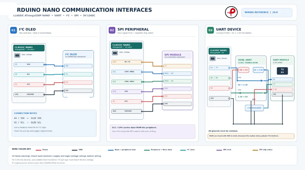
UART, I2C and SPI all move data, but they suit different connections.
| Feature | UART | I2C | SPI |
|---|---|---|---|
| Signal pins | RX, TX | SDA, SCL | MOSI, MISO, SCK, SS |
| Shared clock | No | Yes | Yes |
| Device selection | Separate serial connection | Device address | Chip-select line |
| Common peripherals | GPS, serial Bluetooth | OLED, RTC, sensors | SD cards, displays, memory |
| Nano pins | D0, D1 | A4, A5 | D10 to D13 |
A GPS receiver that sends position data is a natural UART application. An OLED and a temperature sensor can share the Nano’s I2C bus when their addresses are compatible. An SD card normally uses SPI, with a dedicated chip-select signal. Our comparison of I2C vs SPI vs UART explains each protocol in more depth.
Before wiring any of these devices, check supply voltage, signal levels, pull-ups and pin assignments in the peripheral’s datasheet.
Arduino Nano Versions Compared
The Nano name covers several boards with different processors and electrical characteristics. A sketch or circuit made for the classic Nano may need changes before it can run on another model.
| Feature | Classic Nano | Nano Every | Nano ESP32 | Nano R4 |
|---|---|---|---|---|
| Main processor | ATmega328P | ATmega4809 | ESP32-S3 | Renesas RA4M1 |
| Architecture | 8-bit AVR | 8-bit AVR | 32-bit Xtensa | 32-bit Arm Cortex-M4 |
| Clock speed | 16 MHz | Up to 20 MHz | Up to 240 MHz | 48 MHz |
| Flash memory | 32 KB | 48 KB | 8 MB external flash | 256 KB |
| SRAM | 2 KB | 6 KB | 512 KB | 32 KB |
| Main logic voltage | 5V | 5V | 3.3V | 5V GPIO |
| Wireless | No | No | Wi-Fi and Bluetooth LE | No built-in Wi-Fi |
Classic Arduino Nano
Choose the original Nano for traditional ATmega328P projects, basic sensor interfaces, 5V electronics and compact controllers. Many established Arduino examples use this board.
Arduino Nano Every
Nano Every uses the ATmega4809, with 48 KB of Flash, 6 KB of SRAM and a clock speed of up to 20 MHz. It keeps the Nano form factor and shares the classic board’s pin layout.
There are peripheral differences. For example, its officially supported PWM pins differ from the classic Nano, so check the Nano Every pinout before reusing a PWM circuit.
Arduino Nano ESP32
Nano ESP32 uses the ESP32-S3 and supports Wi-Fi and Bluetooth LE. Its GPIO signals operate at 3.3V.
It uses a USB-C connector and has a VBUS connection rather than the conventional 5V pin found on the classic Nano. VBUS availability also depends on the board’s power source. Do not connect 5V signals directly to ESP32 GPIO. The ESP32 pinout guide covers ESP32 GPIO limits.
Arduino Nano R4
Nano R4 uses the Renesas RA4M1 at 48 MHz. It includes a 14-bit ADC, a 12-bit DAC, a built-in RTC and USB-C connectivity.
Its main GPIO operates at 5V. The onboard Qwiic connector uses 3.3V I2C logic, and CAN communication requires an external transceiver.
If you are replacing a classic Nano in an existing circuit, compare the complete pinout and electrical requirements first. Matching dimensions alone do not make two boards interchangeable.
Arduino Nano PCB Design and Implementation
Once a breadboard circuit works, the next step may be a carrier PCB. A carrier board holds the Nano module in place and provides proper connectors for its sensors, power supply and external loads.
The design can be quite simple. A small board may only provide headers and a few connectors. A more developed carrier can add a voltage regulator, signal conditioning and driver circuits.
Arduino Nano PCB Footprint
Arduino’s mechanical documentation lists the Nano PCB outline as approximately 43.16 × 17.76 mm, with a 2.54 mm pin pitch. The product dimensions are commonly rounded to 45 × 18 mm.
Use the official CAD files rather than tracing a photograph to create the footprint. The connector spacing and board outline need to match the actual module.
Design Considerations for a Nano Carrier Board
Header positions
Check both header rows against the Nano’s mechanical drawing. Even a small alignment error can make the module difficult to install or put stress on the header solder joints.
Power distribution
Calculate the current needed by the Nano and every connected peripheral. A motor, relay or solenoid should have a suitable driver and supply arrangement.
Ground routing
Keep the ground connection reliable. High-current return paths from motors and relays should not share a narrow trace with sensitive analog sensor grounds.
Decoupling
Place suitable decoupling capacitors near the power pins of external ICs. Add bulk capacitance where the load or power supply requires it.
Programming access
Leave enough clearance for the Mini-B USB connector and reset button. Consider how the firmware will be updated after the assembly is installed in an enclosure.
External connections
Add suitable protection for signals that leave the PCB through long wires or exposed connectors. The required protection depends on the environment and the expected voltage spikes.
Designing a PCB Around the ATmega328P
A carrier board uses the complete Nano module. A standalone ATmega328P PCB removes the development board and places the microcontroller directly on the new circuit board.
That requires several additional components. The design needs a suitable clock source, reset circuitry, supply decoupling and a programming interface.
You also need to decide how firmware will be loaded. A USB-to-serial circuit and bootloader can provide a familiar upload process. An ISP connection through the ICSP signals provides another programming option.
For a first production-style PCB, keeping the Nano module installed can simplify debugging and replacement. Once the circuit is stable, the standalone microcontroller design can be evaluated.
Common Arduino Nano Problems and Troubleshooting
A few checks can save a lot of time when the board does not behave as expected.
| Problem | Possible cause | What to inspect |
|---|---|---|
| Nano does not power on | Incorrect USB or VIN supply | Check voltage, polarity and cable |
| LED does not respond | Wrong pin or LED polarity | Check D13, resistor and code |
| Analog input stays at zero | Sensor output is grounded or disconnected | Measure voltage at A0 |
| I2C device is not detected | SDA/SCL wiring or power problem | Check A4, A5 and module voltage |
| SPI peripheral does not respond | Incorrect data or chip-select wiring | Check D10 to D13 |
| UART output is unreadable | Baud-rate mismatch | Match the serial settings |
| Sketch upload fails | Incorrect port, cable or driver | Check IDE selection and USB interface |
| Nano resets when a motor starts | Supply dip or electrical noise | Separate the motor supply and add suitable protection |
| Regulator gets hot | High VIN and heavy load | Check regulator dissipation and load current |
| Sensor readings fluctuate | Noise, wiring or reference instability | Check grounding, shielding and ADC reference |
When a project stops working, disconnect the peripherals and test the Nano with a simple Blink sketch. Measure its power rails, then reconnect one module at a time. This helps isolate the faulty connection without changing several things at once.
Arduino Nano Pinout FAQs
What is an Arduino Nano used for?
The Arduino Nano is used in sensor monitoring, robotics, small automation controllers, data logging and embedded electronics projects. Its breadboard-friendly layout is useful when a project needs a compact microcontroller.
How many pins does the classic Arduino Nano have?
It has 30 header positions, arranged in two rows of 15. These provide 14 dedicated digital I/O pins and 8 analog inputs. A0 to A5 can also operate as digital GPIO, while A6 and A7 are analog-input-only.
Is the Arduino Nano a 5V or 3.3V board?
The classic ATmega328P Nano is a 5V board with 5V logic. Its separate 3.3V output can supply compatible peripherals, up to the specified 50 mA maximum.
What are the PWM pins on Arduino Nano?
D3, D5, D6, D9, D10 and D11 support PWM output. The analogWrite() function controls the duty cycle from 0 to 255 on the classic Nano.
What are the I2C pins on Arduino Nano?
A4 is SDA and A5 is SCL. These connections are used by I2C displays, sensors, RTC modules and other compatible peripherals.
What are the SPI pins on Arduino Nano?
D10 is SS, D11 is MOSI/COPI, D12 is MISO/CIPO and D13 is SCK.
Can A6 and A7 be used as digital pins?
No. A6 and A7 on the classic Nano provide analog input only. They cannot be configured as normal digital GPIO.
How much current can an Arduino Nano pin provide?
Arduino specifies 20 mA per I/O pin for the classic Nano. The microcontroller’s absolute maximum rating is not a safe operating target.
Can Arduino Nano run without USB?
Yes. The classic Nano can receive external power through VIN or a correctly regulated 5V supply through the 5V rail. Follow the board’s power specifications.
Can Arduino Nano directly control a motor or relay?
The GPIO pins should provide control signals only. Use a suitable MOSFET, transistor or motor driver for the load, with appropriate protection for inductive switching.
Can Arduino Nano be installed on a custom PCB?
Yes. The complete Nano module can be installed on a carrier PCB using matching header positions. You can also build a standalone ATmega328P circuit with its own clock, reset, power and programming circuitry.
What is the difference between Arduino Nano and Nano Every?
The classic Nano uses an ATmega328P at 16 MHz. Nano Every uses an ATmega4809 at up to 20 MHz and has more Flash and SRAM. They share the Nano form factor and pin layout, but some peripheral features differ.
What is the difference between Arduino Nano and Nano ESP32?
The classic Nano uses a 5V ATmega328P, while Nano ESP32 uses a 3.3V ESP32-S3 with built-in Wi-Fi and Bluetooth LE. Their power connections and GPIO voltage requirements are different.
How can I test a damaged Arduino Nano pin?
Disconnect the external circuit and check the pin with a simple output test using a resistor and LED. Measure the voltage with a multimeter, then compare it with a known working pin using the same test circuit. A failed pin may indicate damage to the microcontroller.
Conclusion
The classic Arduino Nano provides a compact way to build and test embedded electronics. Its digital pins handle control signals, the analog inputs read sensor voltages, and the UART, I2C and SPI interfaces connect a wide range of external modules.
Pin selection matters when several peripherals share the board. Check the alternate functions of each connection, keep the power rails within their specified limits and use external driver circuits for loads such as motors and relay coils.
For a project that starts on a breadboard and eventually moves to a custom PCB, the Nano is a useful development platform. The official pinout and mechanical drawings provide the starting point for that design.
Technical References
- Arduino StoreArduino Nano Official Product Specifications
- Arduino DocsArduino Nano Official Documentation and Pinout
- Arduino SupportArduino PWM Output Reference
- Arduino DocsArduino Nano Every Documentation
- Arduino DocsArduino Nano ESP32 User Manual
- Arduino DocsArduino Nano R4 Documentation