








I2C, SPI, and UART are the three serial communication protocols used to move data between microcontrollers, sensors, and peripheral chips. SPI is the fastest, supporting tens of megabits per second over four wires and one master with multiple slaves. I2C uses only two wires and supports many devices on the same bus through addressing, but tops out around 3.4 Mbps in high speed mode. UART is the simplest, a two wire, point to point, asynchronous link with no clock line, commonly used for debugging and connecting modules like GPS or Bluetooth. Choose SPI for raw throughput, I2C for multi device wiring simplicity, and UART for simple point to point links.
I have spent more than eight years designing embedded hardware, and the single question I get asked most often by junior engineers and hobbyists alike is some version of “i2c protocol vs spi vs uart, which one should I use.” It sounds like a simple question. It rarely has a simple answer, because the right serial communication protocol depends on your sensor count, your required data rate, your board layout, and your power budget.
This guide is written from the perspective of someone who has actually debugged a stuck I2C bus at 2 a.m. before a production deadline, who has watched a UART baud rate mismatch turn readable text into garbage characters, and who has traced SPI clock skew on an oscilloscope to find out why a display was flickering. My goal is to give you a comparison that goes beyond textbook definitions and actually helps you pick the right bus for your embedded communication protocols stack.
We will cover every angle: uart vs spi vs i2c speed, wiring complexity, power draw, error handling, and the practical decision framework I use on real embedded systems and IoT projects. If you are building a product and need help translating this decision into a working board, our embedded systems development team runs through exactly this kind of protocol selection on every project.
What Is UART Communication Protocol
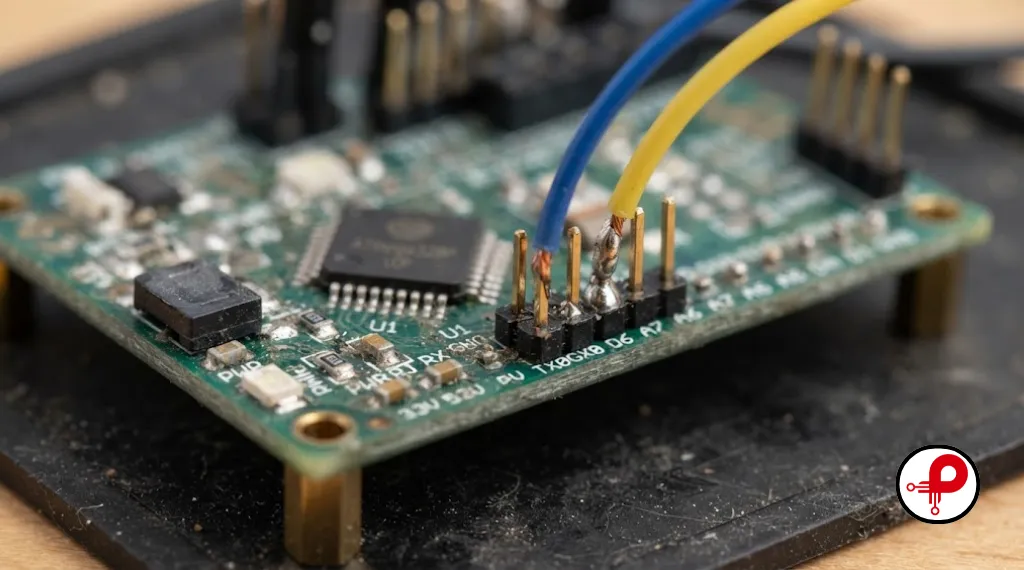
UART stands for Universal Asynchronous Receiver Transmitter. Unlike I2C and SPI, UART is not really a bus protocol in the traditional sense, it is a physical circuit built into a microcontroller that converts parallel data from the CPU into a serial bit stream and back again.
Key Characteristics of UART
There is no shared clock signal in SPI style synchronization. Both sides agree on a baud rate ahead of time.
TX (transmit) and RX (receive) must be cross connected between devices.
A standard UART communication protocol link connects exactly two devices.
Supports full duplex communication and half duplex communication depending on implementation.
Frame structure includes a start bit, data bits, an optional parity bit, and one or more stop bits.
Baud rates can be configured to match application speeds, commonly ranging from 9600 up to several megabauds.
Where UART Shows Up in Real Products
UART is everywhere in debugging. Nearly every microcontroller communication protocols stack includes at least one UART port wired to a USB to serial bridge for console output. It is also the native interface for many GPS modules, Bluetooth classic modules, RFID readers, and industrial RS232 or RS485 equipment (RS485 layers a differential physical layer on top of asynchronous serial communication for long distance noise immunity).
Because there is no clock line, uart baud rate must match exactly on both ends, commonly 9600, 115200, or higher. Get the baud rate wrong and you get nothing but garbled characters on the terminal, one of the most common first debugging exercises in embedded systems communication.
What Is SPI Communication Protocol
SPI, or Serial Peripheral Interface, is a synchronous serial communication protocol developed by Motorola. It is the protocol I reach for whenever raw throughput matters more than pin count.
The Four SPI Signal Lines
Data line transmitting information from the master to the slave.
Data line transmitting information from the slave to the master.
The clock signal generated by the master to synchronize data transmission in SPI.
Dedicated control line per slave device used by the master to enable communication.
Allows simultaneous transmission and reception of data over MOSI and MISO lines.
Relies on a shared clock signal provided by the master rather than pre-agreed baud rates.
Why Engineers Choose SPI
SPI supports true full duplex communication, meaning master and slave can send data simultaneously on MOSI and MISO. Combined with a master driven clock, this gives spi data transfer rates that comfortably reach tens of megabits per second, and specialty peripherals can push well past 60 Mbps. There is no addressing overhead and no arbitration, so protocol logic stays simple even at high clock speeds.
The tradeoff is wiring. Every additional slave device needs its own dedicated chip select line, so a bus with five peripherals needs four shared lines plus five separate CS lines. This is the classic tradeoff you weigh in spi vs i2c protocol decisions: SPI is faster, I2C is leaner on pins.
SPI is the dominant choice for SPI flash memory, SD card SPI interface connections, fast ADC and DAC chips, and graphical displays where a full frame buffer has to move quickly. If your product involves high resolution displays or external flash, our PCB design services team can help route these high speed lines correctly on your board.
What Is I2C Communication Protocol
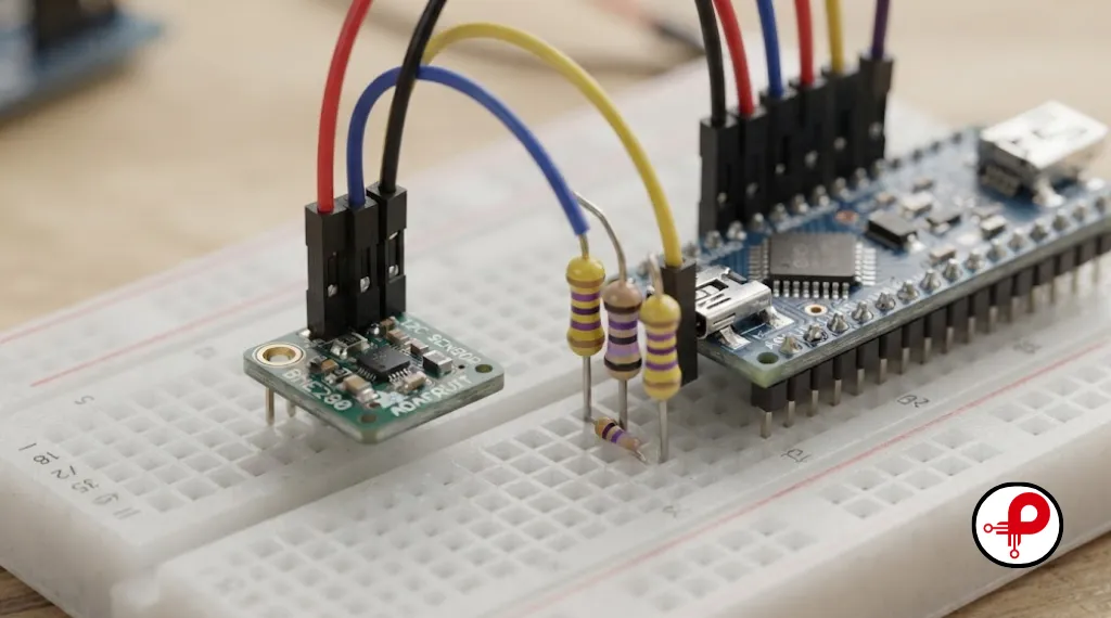
I2C, or Inter Integrated Circuit protocol, was developed by Philips (now NXP) to connect multiple low speed peripherals using as few pins as possible.
The Two I2C Signal Lines
- SDA (Serial Data): carries data in both directions
- SCL (Serial Clock): the shared clock line, always driven by the master
Both lines are open drain and require pull up resistors, which is a detail that trips up a lot of first time board designers. Every device on the bus shares just these two wires, and each slave is identified by a unique i2c address, typically 7 bits, giving up to 112 usable addresses after reserved ranges are excluded.
I2C Speed Modes
I2C supports several speed grades: Standard mode at 100 kbps, Fast mode at 400 kbps, Fast mode plus at 1 Mbps, and High speed mode reaching 3.4 Mbps. In practice, most designs settle on Standard or Fast mode because bus capacitance limits how far you can push clock stretching in i2c and rise time before signal integrity suffers.
Why I2C Wins on Wiring
The real win with I2C is scalability without extra pins. Ten sensors on an I2C bus still only need two wires plus power and ground. This is why I2C dominates connections for sensors using I2C, real time clocks, EEPROMs, and small OLED I2C display modules. If you are laying out a sensor heavy board, I2C keeps your trace count and connector size manageable, something our electronic hardware design engineers weigh heavily during early schematic reviews.
UART vs SPI vs I2C Comparison Table
| Feature | UART | SPI | I2C |
|---|---|---|---|
| Number of wires | 2 (TX, RX) | 4 minimum (MOSI, MISO, SCK, CS) plus 1 CS per device | 2 (SDA, SCL) |
| Typical speed | Up to ~1 Mbps practical | 10 to 60+ Mbps | 100 kbps to 3.4 Mbps |
| Clock signal | None (asynchronous) | Yes, master driven | Yes, master driven |
| Communication type | Full or half duplex | Full duplex | Half duplex |
| Devices supported | 1-to-1 only | Multiple, one CS line each | Multiple, addressed on shared bus |
| Wiring complexity | Low | Moderate to high with many devices | Low even with many devices |
| Error checking | Optional parity bit | None built in | ACK/NACK bit per byte |
| Power consumption | Low | Medium to higher at speed | Low |
| Common use cases | Debug console, GPS, Bluetooth modules | Flash memory, SD cards, displays, fast ADCs | Sensor networks, RTC, EEPROM, small displays |
| Pull up resistors needed | No | No | Yes, required |
| Distance tolerance | Longer with RS485 variant | Short, board level | Short, board level |
I2C vs SPI Speed: A Detailed Breakdown
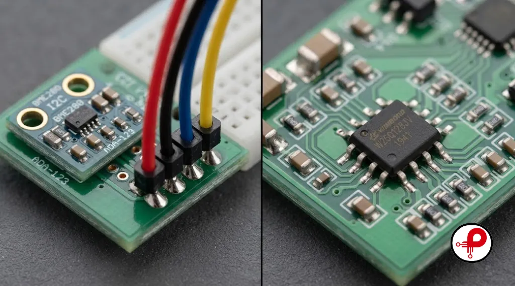
When engineers search for i2c vs spi speed or uart vs spi vs i2c speed, they are usually trying to solve a bottleneck. Here is how the three protocols actually stack up in the field, not just on a datasheet.
SPI wins on raw throughput. A decent SPI peripheral pushes 20 to 60 Mbps without any special tuning, and dedicated flash or ADC parts can clock well past 100 MHz on short traces. This is why spi vs uart communication is never really a contest for high bandwidth sensor arrays, video peripherals, or memory devices.
I2C is the middle ground. Fast mode at 400 kHz is the sweet spot most designs actually use in production. High speed mode exists on paper at 3.4 Mbps, but very few off the shelf sensors implement it, and bus capacitance (a rough rule of thumb is 400 pF maximum for Fast mode) limits both trace length and device count as you push speed higher.
UART is the slowest in raw numbers, and the asynchronous serial communication framing (start bit, stop bit, optional parity) adds roughly 20 percent overhead on top of the nominal baud rate. That said, UART’s simplicity often makes it “fast enough” for its intended job, since it usually isn’t moving bulk data, it is moving commands, GPS sentences, or log text.
Practical verdict: SPI > I2C > UART for raw speed, but the “fastest” protocol is rarely the deciding factor. Wiring, device count, and firmware complexity usually decide the winner first.
One detail engineers often overlook is that datasheet maximum speed and real world achievable speed are two different numbers. A sensor rated for 400 kHz Fast mode I2C may only be reliable at 100 kHz once you account for trace length, connector impedance, and the pull up resistor value you actually populated. Likewise, an SPI flash chip rated at 100 MHz may need to be clocked much lower if the board was not designed with controlled impedance and short, matched trace lengths in mind. Always validate real world timing on a scope or logic analyzer rather than trusting the datasheet ceiling blindly, especially on a first hardware revision.
Wiring and Pin Count Differences
This is where I2C separates itself from the pack. Consider connecting five slave devices to a microcontroller:
UART Multi-Device Scaling
Not possible on a single bus. You need five separate UART peripherals or a multiplexer, consuming numerous MCU pins.
SPI Multi-Device Scaling
Requires a shared clock and data pair, plus one dedicated chip select line per connected peripheral device.
I2C Multi-Device Scaling
Utilizes just two common wires, SDA and SCL, allowing multiple devices on the same bus without extra pins.
Bus Address Management
I2C relies on unique hardware addresses, whereas SPI uses distinct chip select lines to isolate individual slaves.
If your board has a tight pin budget, especially on smaller microcontroller communication protocols targets like an 8 pin or 20 pin MCU, I2C is almost always the pragmatic choice. If pin count is not a constraint and you need speed, SPI’s extra wiring is a fair trade. Getting this tradeoff wrong late in a design cycle is one of the more expensive mistakes we see, which is why protocol selection belongs in the early electronic product design workflow rather than being bolted on after layout starts.
Power Consumption Compared
For battery powered and IoT communication interfaces, power draw matters as much as speed.
Protocol Power Efficiency & Consumption Matrix
UART Power Profile
Generally the most power efficient protocol available. It features no continuously toggling clock line, and microcontrollers easily support deep sleep with instant wake on UART activity.
I2C Power Profile
Stands close behind UART in terms of efficiency. The clock only toggles during active data transfers, keeping bus idle current exceptionally low despite minimal pull-up resistor bleed.
SPI Power Profile
Tends to draw the highest power at speed because a continuously clocked, full-duplex, high-frequency bus toggles transistors constantly, requiring strategic protocol choices.
Verdict: UART > I2C > SPI for power efficiency in most real designs, though this can flip depending on how aggressively you clock gate each peripheral.
Master Slave Architecture and Multi Device Support
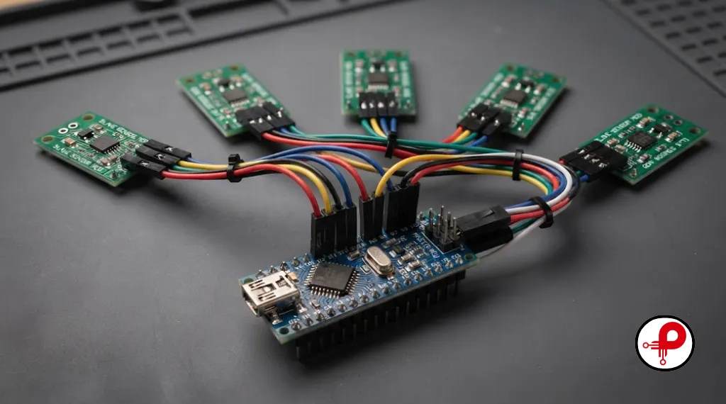
All three protocols rely on some form of master slave communication, but they implement it very differently.
SPI uses a single master with dedicated chip select lines, meaning the master explicitly decides which slave is “listening” at any moment. There is no addressing scheme, which keeps the protocol logic simple but limits scalability without extra pins.
I2C uses a shared bus with software addressing. The master sends a start condition followed by a 7 bit (or 10 bit) i2c address, and only the matching device responds. This is what makes I2C so pin efficient for sensor networks, and it also supports multi master configurations, something SPI does not do cleanly out of the box.
UART has no real master slave concept at all, it is simply two peers talking to each other over dedicated TX and RX lines. Any “hierarchy” is defined purely at the application layer, not the protocol layer.
Data Integrity and Error Handling
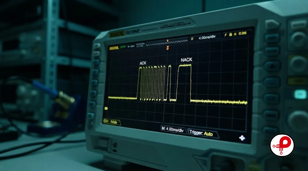
- UART offers an optional parity bit for single bit error detection, plus start and stop bit framing that helps a receiver detect misalignment. It has no retry mechanism.
- SPI has no built in error checking at all. If you need integrity guarantees, you implement checksums or CRC in firmware yourself.
- I2C includes a mandatory ACK/NACK bit after every byte, which gives the master immediate confirmation that a slave received and understood the data. This built in acknowledgment is one reason I2C feels more “robust” during bring up, even though it is not immune to bus lockups caused by clock stretching in i2c or a slave holding SDA low.
If your application genuinely needs guaranteed delivery and multi node robustness in noisy environments, protocols built on top of these three, like CAN or Modbus over RS485, are usually a better fit than trying to bolt reliability onto SPI or UART after the fact.
When to Use UART vs SPI vs I2C
Here is the decision framework I actually use on new hardware projects, distilled to when to use uart vs spi vs i2c in plain terms.
Protocol Selection & Quick Decision Checklist
Choose UART when:
- You need the simplest possible two device link
- Your peripheral only speaks UART (GPS, Bluetooth module, cellular modem, debug console)
- You need to interface with legacy RS232 or RS485 industrial equipment
- Pin count and firmware complexity both need to stay minimal
Choose SPI when:
- You need maximum throughput (displays, SD cards, flash memory, fast ADCs)
- You are working with a small, fixed number of devices where extra CS pins are acceptable
- Full duplex, simultaneous send and receive is a requirement
- Tight timing and low latency matter more than pin count
Choose I2C when:
- Pin count is limited and you have several peripherals to connect
- Speed requirements are modest (most sensors, RTCs, EEPROMs, and small OLED displays fit comfortably)
- You want to keep wiring dead simple as the design scales
- You need multi master capability or want built in ACK/NACK error signaling
Quick Decision Checklist
Most real embedded products use all three protocols on the same board: UART for debug and modules, I2C for sensors, SPI for the display or flash. Planning this bus layout early, ideally during schematic capture, saves significant rework later. This is a core part of what we cover in electronic hardware design engagements.
Real World Examples on Arduino, ESP32, STM32, and Raspberry Pi
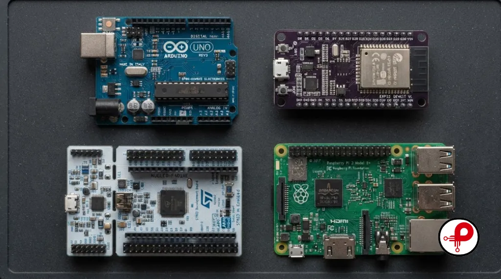
Arduino communication protocols: The Wire library handles I2C, the SPI library handles SPI, and Serial handles UART. A typical Arduino project might read a BME280 sensor over I2C, drive an SD card over SPI, and print debug data over UART simultaneously.
ESP32 SPI communication and ESP32 I2C communication: The ESP32 exposes flexible pin mapping for both buses through its GPIO matrix, which is genuinely one of its best features for embedded prototyping. If you are setting up an ESP32 project for the first time, our guide on the ESP32 board URL for Arduino IDE walks through the initial toolchain setup before you even touch peripheral wiring.
STM32 UART communication: STM32 microcontrollers expose multiple hardware UART peripherals, commonly used alongside DMA for high throughput logging without blocking the CPU, a pattern we see often in medical and industrial designs where reliable, non blocking serial communication protocols matter, similar to considerations in our medical device development work.
Raspberry Pi SPI and Raspberry Pi I2C: The Raspberry Pi’s GPIO header exposes both a hardware SPI bus and an I2C bus, enabling it to drive SPI flash memory, TFT displays, and I2C sensor boards directly from Linux userspace with tools like i2c-tools for bus scanning and debugging.
Common Mistakes Engineers Make
1. Forgetting I2C pull up resistors
SDA and SCL are open drain, without external pull ups the bus simply will not work, or will work intermittently depending on parasitic capacitance.
2. Mismatched UART baud rate
The number one cause of garbled serial console output, always double check both ends agree on speed, parity, and stop bits.
3. Sharing a chip select incorrectly on SPI
Forgetting to deassert CS on unused devices can cause bus contention and corrupted transfers.
4. Overloading an I2C bus electrically
Adding too many devices, or running long traces, pushes bus capacitance past the 400 pF Fast mode guideline and causes signal integrity failures that are hard to diagnose without a scope.
5. Assuming SPI has error checking
It does not. Skipping a CRC or checksum layer on critical data leaves you blind to corrupted transfers.
6. Ignoring clock polarity and phase (CPOL/CPHA)
Two SPI devices that disagree on clock mode will exchange garbage even though wiring looks correct.
7. Routing high speed SPI lines poorly on the PCB
Long, unmatched traces at high SPI clock speeds introduce ringing and timing violations. Careful PCB design and layout discipline matters more as SPI clock speed increases.
Best Practices Checklist
- Always add pull up resistors to I2C lines, typically 2.2k to 10k ohms depending on bus speed and capacitance
- Keep SPI trace lengths short and matched when clocking above a few tens of MHz
- Use a logic analyzer or scope early during bring up rather than guessing at protocol level bugs
- Document every I2C address in your schematic to avoid silent address collisions when adding new sensors
- Add firmware level timeouts on I2C transactions to recover gracefully from a stuck bus
- Validate UART baud rate tolerance against your crystal or oscillator accuracy, especially at high baud rates
- Plan bus topology (which protocol serves which peripheral) during schematic review, not after layout
- Run functional PCB testing and inspection on every communication bus before committing to production
- Choose components with your protocol requirements in mind during electronic component selection, since swapping a SPI only flash chip for an I2C part late in the design is rarely painless
Frequently Asked Questions
1. What is the fundamental operational difference between I2C, SPI, and UART?
↑2. Which protocol yields the highest throughput, and what are their typical real-world speed ceilings?
↓3. How do I choose between I2C and SPI when designing a multi-sensor printed circuit board?
↓4. Can I2C and SPI coexist harmoniously on the same microcontroller board?
↓5. Why doesn’t UART require a clock signal, and how do receiving nodes maintain data synchronization?
↓6. What physical constraints dictate the maximum number of devices supported on an I2C bus?
↓7. Which protocol minimizes trace routing complexity, and how do wire counts scale with added peripherals?
↓8. How do SPI and I2C handle error checking and data integrity at the protocol layer?
↓9. What are the primary failure modes regarding signal integrity and distance limitations for board-level protocols?
↓10. When should external pull-up resistors be implemented, and what determines their optimal electrical value?
↓Conclusion and Next Steps
After eight plus years of shipping embedded hardware, my honest take on i2c protocol vs spi vs uart is that there is no universal winner, only the right tool for a specific job. UART earns its place for simple debug links and modules that only speak serial. SPI earns its place when you need speed and can spare the extra pins. I2C earns its place when you are wiring up a sensor heavy board and want to keep your pin count and PCB routing sane.
The protocols rarely compete head to head in a finished product, they cooperate. A well designed embedded system typically uses all three, each carrying the traffic it is best suited for.
If you are starting a new hardware project and want an engineering team that thinks through bus architecture, component selection, and PCB layout together rather than as separate afterthoughts, our team can help across the full journey, from product development strategy through prototyping services and production. Reach out to talk through your protocol and board architecture before you commit to a schematic, it is the cheapest stage to get this decision right.
For deeper technical reference on protocol electrical specifications, see the datasheets and application notes published by Texas Instruments, Analog Devices, Microchip Technology, and Arm, and for peer reviewed comparative analysis, the IEEE Xplore digital library publishes ongoing research on serial bus performance and reliability.