







Medical device development is one of the most demanding disciplines in engineering, and for good reason. A single design flaw, a poorly grounded PCB trace, or a missed verification step can put a patient’s life at risk and cost a company years of rework. Having spent more than eight years working alongside hardware engineers, regulatory consultants, and startup founders on connected health products, I have watched brilliant ideas stall not because the concept was weak, but because the team underestimated what medical device development actually requires.
This guide breaks down the entire medical device development process, from the first sketch on a whiteboard to a fully certified product on a hospital shelf. Whether you are a startup founder validating an idea, a biomedical engineer managing your first design history file, or a procurement lead comparing medical device development services, this article gives you the practical roadmap that most blog posts skip.
What Is Medical Device Development
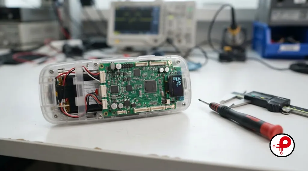
Medical device development is the structured process of turning a healthcare need into a safe, effective, and legally marketable product. It spans everything from concept sketches and biomedical engineering research to embedded systems design, PCB design, firmware development, clinical testing, and regulatory documentation.
Unlike a typical consumer gadget, a medical device carries a legal and ethical obligation to protect the patient using it. That obligation shapes every decision in the medical device design and development process, from the tolerances on a mechanical part to the way a firmware engineer handles a sensor fault. Whether the end product is a diagnostic medical device, a wearable medical device, or a piece of hospital equipment, the underlying discipline is the same: design controls, documented evidence, and rigorous testing at every stage.
Why Medical Device Product Development Is Different From Ordinary Product Design
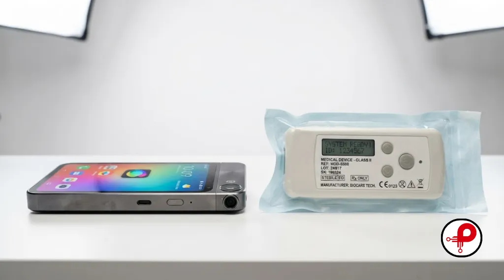
Consumer electronics teams can ship fast and patch later. Medical device engineering teams cannot. A firmware bug in a smartwatch is an inconvenience; a firmware bug in an infusion pump can be catastrophic. That single difference drives almost everything unique about medical device product development:
Every requirement must be traceable from a documented design input to a verified design output, ensuring full accountability throughout the development lifecycle.
Electronic hardware decisions are judged not just on raw performance, but on critical factors like patient safety, electrical insulation, and electromagnetic compatibility (EMC).
Every supplier, contract manufacturer, and individual component in the supply chain must be formally integrated into a regulated quality system.
Monitoring continues long after the device ships, as regulators mandate that manufacturers track real-world performance and user complaints.
Teams that treat medical device development like a standard consumer product build sprint almost always hit a wall during design verification and validation, when a regulatory reviewer or a notified body asks for evidence the team never collected.
The Medical Device Development Lifecycle: 10 Stages Explained
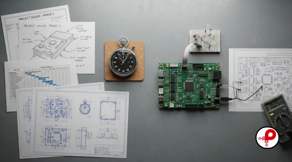
Most successful projects follow a recognizable medical device development lifecycle, even if the terminology varies slightly between companies. Here is the version I use with clients, based on ISO 13485 design controls and FDA design control expectations.
| Stage | Primary Goal | Typical Deliverable |
|---|---|---|
| 1. Needs Assessment | Define the clinical problem and user needs | User needs document |
| 2. Design Inputs | Translate needs into measurable requirements | Design input specification |
| 3. Concept and Architecture | Choose the mechanical, electrical, and software approach | System architecture diagram |
| 4. Medical Device Prototyping | Build and test early proof of concept units | Functional prototype |
| 5. Detailed Design | Finalize PCB design, firmware, and mechanical CAD | Engineering drawings, schematics |
| 6. Risk Analysis | Identify and mitigate hazards | ISO 14971 risk file |
| 7. Verification and Validation | Confirm the device meets inputs and user needs | V&V test reports |
| 8. Regulatory Submission | Prepare and file with FDA or a notified body | 510(k), PMA, or technical file |
| 9. Manufacturing Transfer | Move from prototype to production tooling | DFM report, pilot production run |
| 10. Post-Market Surveillance | Monitor field performance and complaints | Post-market surveillance plan |
Each stage feeds the next. Skipping ahead, for example moving to production tooling before design verification is complete, is the single most common reason medical device development timelines blow past their budget.
Medical Device Design and Engineering in Detail
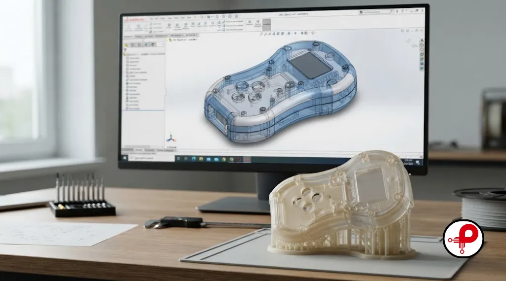
Medical device design sits at the intersection of mechanical engineering, electronic hardware design, and software. A strong design phase answers three questions before a single line of firmware is written: what does the device need to measure or do, how will it interface with the human body or clinical environment, and what could go wrong.
Mechanical and Industrial Design
Enclosure geometry, biocompatible materials, ingress protection ratings, and ergonomics all matter here, especially for wearable medical devices and handheld diagnostics. Our guide on industrial product design engineering covers how mechanical decisions ripple through manufacturability and cost.
Embedded Systems and Firmware
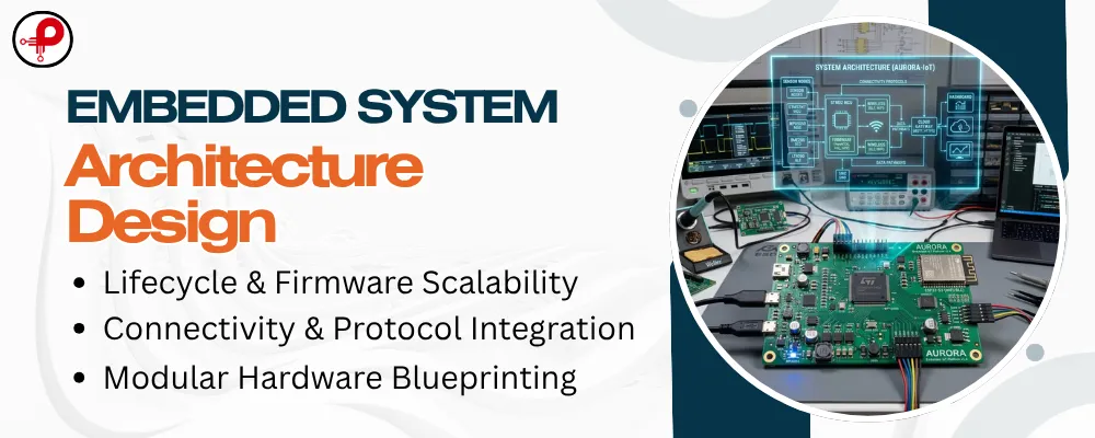
Medical hardware design almost always includes an embedded microcontroller managing sensors, communication, and safety interlocks. Firmware for a medical device needs deterministic behavior, watchdog timers, and fail-safe states, which is a very different mindset from consumer firmware where a reboot is an acceptable fallback.
Human Factors and Usability Engineering
Human factors engineering is not optional for most Class II and Class III devices. It requires simulated use testing with representative users to prove the device can be used safely and effectively, including under stress or by clinicians with limited training time. This is one of the newer areas of scrutiny for the FDA, and submissions that lack solid usability evidence are increasingly flagged during review.
For a broader view of how these engineering disciplines fit together outside the medical space, see The Complete Electronic Product Design Workflow and our consumer electronics product design guide, which explain the same design principles applied to non-regulated products.
Electronic Hardware and PCB Design for Medical Devices
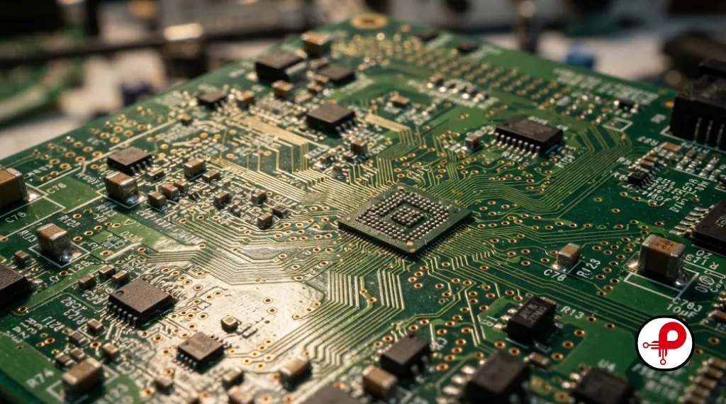
This is the section most generic articles skip, and it is where medical device development projects most often go wrong. A medical PCB is not just a circuit that works on the bench. It has to survive electrical safety testing, EMC testing, and years of field use without drifting out of tolerance.
PCB Design vs PCB Layout
People often use these terms interchangeably, but they are different disciplines. PCB design covers schematic capture, component selection, and circuit topology, while PCB layout is the physical placement and routing of copper on the board. Our breakdown of PCB design vs PCB layout explains why medical device teams need both skill sets represented, ideally by engineers who talk to each other daily rather than handing off a netlist and hoping for the best.
IPC Standards and Design for Manufacturability
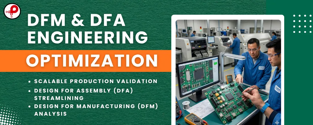
Medical boards should be designed against IPC-2221 and IPC-6012 class 2 or class 3 requirements depending on the criticality of the application. Designing for manufacturability, or DFM, early in the layout phase avoids costly re-spins once the board reaches contract manufacturing. Key DFM considerations include:
Ensure adequate clearance between high-voltage and low-voltage nets to prevent arcing and maintain electrical safety.
Maintain controlled trace widths for all power paths to minimize resistance and prevent excessive heating.
Utilize a defined stack-up with dedicated, continuous ground and power planes to ensure signal integrity and EMI control.
Specify via sizes appropriate for the required current and total thermal load of the design to ensure long-term reliability.
Our PCB layout best practices and circuit board design rules articles go deeper into stack-up planning, clearance rules, and routing strategy, all of which apply directly to medical hardware.
EMI, EMC, and Signal Integrity
Electromagnetic compatibility is one of the most common reasons a medical device fails certification testing. Poor grounding, unshielded switching regulators, and long unmatched traces on high-speed signals all create EMI problems that are far cheaper to solve on paper than after a board has already been fabricated. If your team is troubleshooting noise issues, our articles on EMI issues, causes, examples, and fixes, electromagnetic compatibility testing, and high frequency switching noise issues walk through practical mitigation techniques.
Custom PCB Design vs Off-the-Shelf Modules
Many early-stage medical device startups start with an off-the-shelf module to move fast, then transition to a custom PCB design as the product matures and cost, size, or regulatory requirements demand it. Our comparison of custom PCB design vs off-the-shelf solutions is a useful reference when deciding which path fits your timeline and budget.
To keep routing decisions grounded in real numbers rather than guesswork, engineers on our team regularly use calculators such as the microstrip impedance calculator built to IPC-2141, the PCB track width calculator, the PCB via current capacity calculator, and the pi attenuator calculator when tuning RF and power circuits.
Avoiding Common Layout Mistakes
Even experienced teams repeat the same handful of errors, from mixed analog and digital return paths to inadequate decoupling near sensitive amplifiers. Our list of frequent PCB design mistakes is worth a read before your board goes to fabrication, not after.
Medical Device Prototyping and Proof of Concept
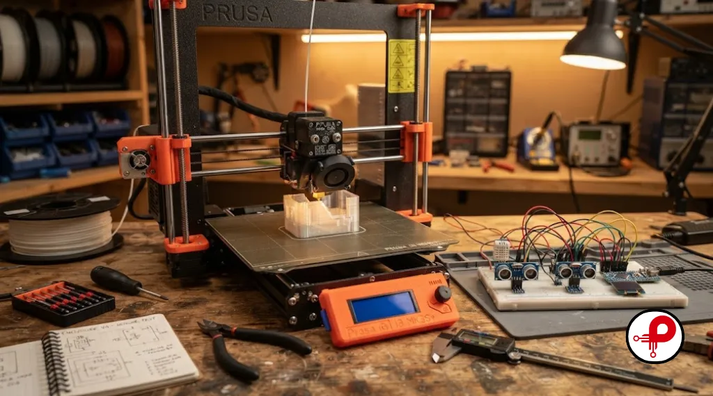
Rapid prototyping lets a team validate an idea before committing to expensive tooling or a full regulatory file. A good medical device prototype answers a specific question: does the sensor read accurately, does the wireless link hold a stable connection, does the mechanical fit work on a real hand or wrist.
Rapid Prototyping Methods
3D Printing
Utilized for enclosures and mechanical fixtures, 3D printing is the ideal choice for iterating quickly on ergonomics and testing physical fit before committing to more permanent manufacturing processes.
CNC Machining
Reserved for higher precision mechanical parts or short-run metal components that require tighter tolerances or material properties that 3D printing cannot achieve.
Breadboard & Dev-Boards
Essential for early-stage proof of concept. These tools allow you to validate circuit logic and basic functionality long before a custom PCB exists or is ready for production.
Off-the-Shelf Platforms
Using ecosystems such as Arduino or similar boards allows teams to validate sensor behavior and software integration quickly, helping to de-risk key subsystems early in the development cycle.
Prototyping Connected and IoT Medical Devices
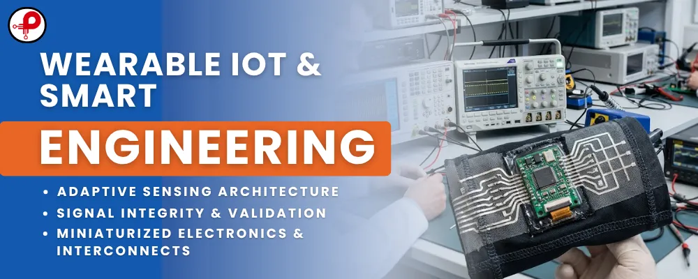
Wearable medical devices and diagnostic devices increasingly rely on wireless connectivity. Whether the product uses Bluetooth Low Energy, Wi-Fi, or a cellular module, prototyping the connectivity layer early avoids surprises later. Our guides on how to build an IoT prototype quickly and how to make a Bluetooth device walk through the practical steps of getting a connected prototype working reliably, including power budgeting and antenna placement, both of which matter enormously for a wearable form factor.
A working prototype also becomes the foundation for design verification testing later, so it is worth documenting test results even at this early stage. Investors, clinical advisors, and regulatory consultants will all ask to see this evidence eventually.
Risk Management and Design Controls

Risk analysis is not a checkbox exercise in medical device development, it is the backbone of the entire quality system. The internationally recognized standard for this work is ISO 14971, which defines how manufacturers identify hazards, estimate risk, and document mitigations across the full product lifecycle.
A practical risk management process includes:
Identify Hazards
Systematically identify foreseeable hazards, including use errors, potential hardware failures, and emerging cybersecurity threats to your device.
Estimate Risk
Evaluate and estimate the severity and probability of occurrence of harm for each identified hazard to prioritize your safety efforts.
Implement Mitigations
Apply design mitigations, protective measures, or clear labeling requirements to reduce identified risks to an acceptable level.
Verify Effectiveness
Perform verification activities to ensure that your implemented mitigations effectively reduce the risk to an acceptable level without introducing new hazards.
Document Residual Risk
Formally document all residual risks and ensure formal sign-off from stakeholders and regulatory leads before the product is released to market.
This process runs in parallel with design controls, not after them. A risk file that gets written retroactively to satisfy a regulatory submission is usually a red flag to reviewers, because it rarely reflects real design decisions.
Regulatory Pathways: FDA, ISO 13485, and Global Compliance
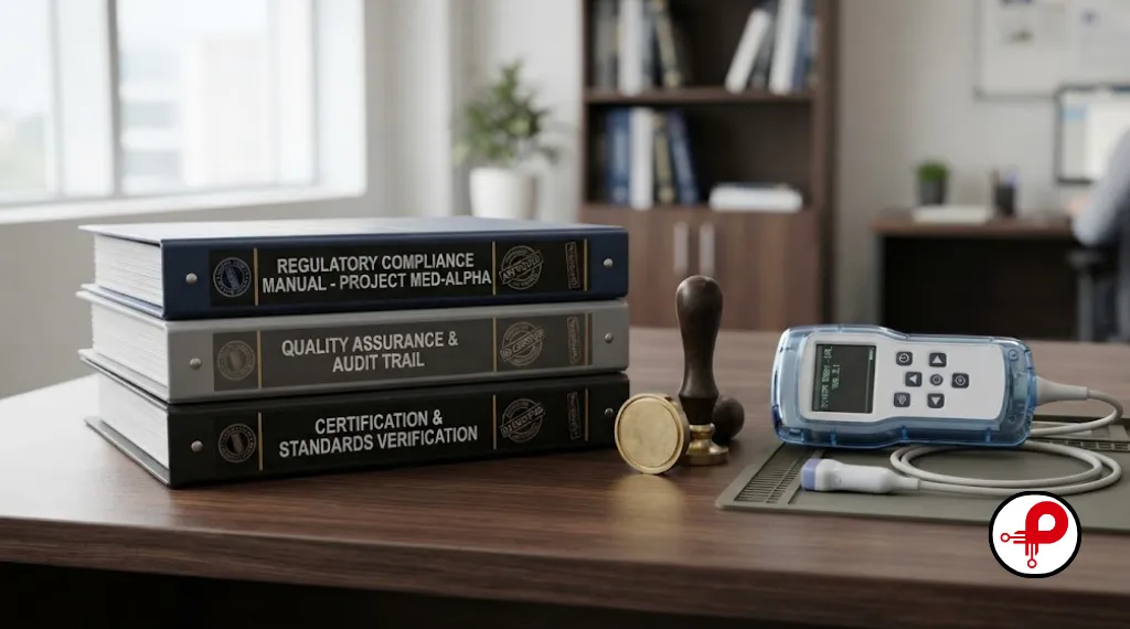
Regulatory strategy should be decided at the start of a project, not after the design is finished. The pathway you choose shapes your testing plan, your documentation, and your timeline.
FDA Pathways in the United States
Most moderate-risk devices in the United States go through the FDA 510(k) premarket notification process, which requires demonstrating that a new device is substantially equivalent to a legally marketed predicate device. Higher-risk Class III devices typically require Premarket Approval (PMA), a more rigorous pathway involving extensive clinical evidence. Devices with no suitable predicate may qualify for the De Novo pathway instead.
In 2026, the FDA has placed increasing emphasis on cybersecurity documentation for any connected or software-driven device, including a software bill of materials and a plan for monitoring post-market vulnerabilities. Teams building IoT medical devices or connected diagnostics should factor this into their engineering documentation from day one rather than bolting it on before submission.
ISO 13485 and Quality Management
ISO 13485 is the internationally recognized quality management standard for organizations involved in designing, manufacturing, and servicing medical devices. Certification is not mandatory everywhere, but it is effectively required to sell into the European Union and is widely expected by hospital procurement teams and investors as proof of a mature quality system.
IEC 60601 and Electrical Safety
For any device with a power source, IEC 60601 sets the baseline requirements for electrical safety and essential performance, covering everything from leakage current limits to mechanical hazards and alarm systems. Devices with software also need to consider IEC 62304 for software lifecycle processes.
Comparison of Common Regulatory Pathways
| Pathway | Typical Device Risk | Clinical Data Required | Approximate FDA Review Time |
|---|---|---|---|
| 510(k) | Low to moderate (Class I/II) | Usually not required | Roughly 90 days for FDA review, longer overall with prep and responses |
| De Novo | Novel, low to moderate risk | Sometimes required | Similar to 510(k) but with added review of novel risk |
| PMA | High risk (Class III) | Extensive clinical trials required | Up to 180 days for FDA review, often longer in practice |
| EU CE Marking (MDR) | All classes | Varies by class | Depends on notified body capacity |
Building this strategy alongside your engineering documentation, rather than after your prototype is finished, is one of the clearest markers of a mature medical device development services provider.
Medical Device Manufacturing and Production Scaling
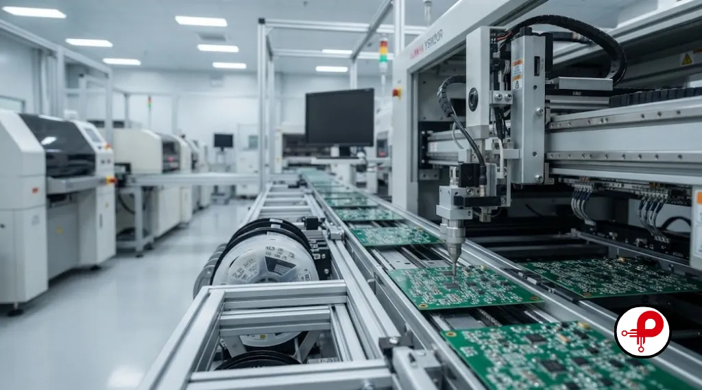
Once a design passes verification and validation, the focus shifts to medical device manufacturing. This stage determines whether a great prototype becomes a reliable, repeatable product.
PCB Manufacturing and Assembly
Transitioning from prototype boards to production volume requires close coordination with a contract manufacturer on panelization, solder paste stencils, and test coverage. Our guides on the PCB manufacturing process and the PCB manufacturing and assembly process explain what happens between a Gerber file and a finished, tested board.
Mechanical Production Methods
- Injection molding for high-volume enclosures once tooling costs are justified by production volume
- CNC machining for low to medium volume runs or components requiring tight tolerances
- 3D printing for jigs, fixtures, and very low volume production or spare parts
Sterilization and Biocompatibility
Devices that contact skin, mucous membranes, or internal tissue require biocompatibility testing under ISO 10993, and any device requiring sterility needs a validated sterilization process, whether that is ethylene oxide, gamma irradiation, or steam autoclave, chosen based on material compatibility.
Supply Chain and Quality Management
A resilient supply chain for medical device manufacturing means qualifying multiple sources for critical components, maintaining incoming inspection procedures, and keeping a clear paper trail for every lot. This is where a documented quality management system earns its keep, since a single unqualified substitute component can trigger a full regulatory investigation if something goes wrong in the field.
In-House vs Outsourced Medical Device Development
One of the most consequential decisions a startup makes is whether to build an internal engineering team or work with a custom medical device development partner. Neither approach is universally better, but the tradeoffs are predictable.
| Factor | In-House Team | Outsourced Development Partner |
|---|---|---|
| Speed to first prototype | Slower to assemble the right team | Faster, since the team already exists |
| Regulatory expertise | Needs to be hired or trained | Often already established |
| Cost at low volume | High fixed cost | Lower upfront, pay for scope |
| Long-term IP control | Full control | Requires clear contractual terms |
| Flexibility across disciplines | Limited to hired skill sets | Access to PCB, mechanical, firmware, and regulatory specialists |
Many successful medical device companies use a hybrid model, keeping core clinical and product strategy in-house while outsourcing specialized medical device engineering services such as PCB design, firmware, or regulatory documentation to an experienced partner.
Common Mistakes in Medical Device Engineering
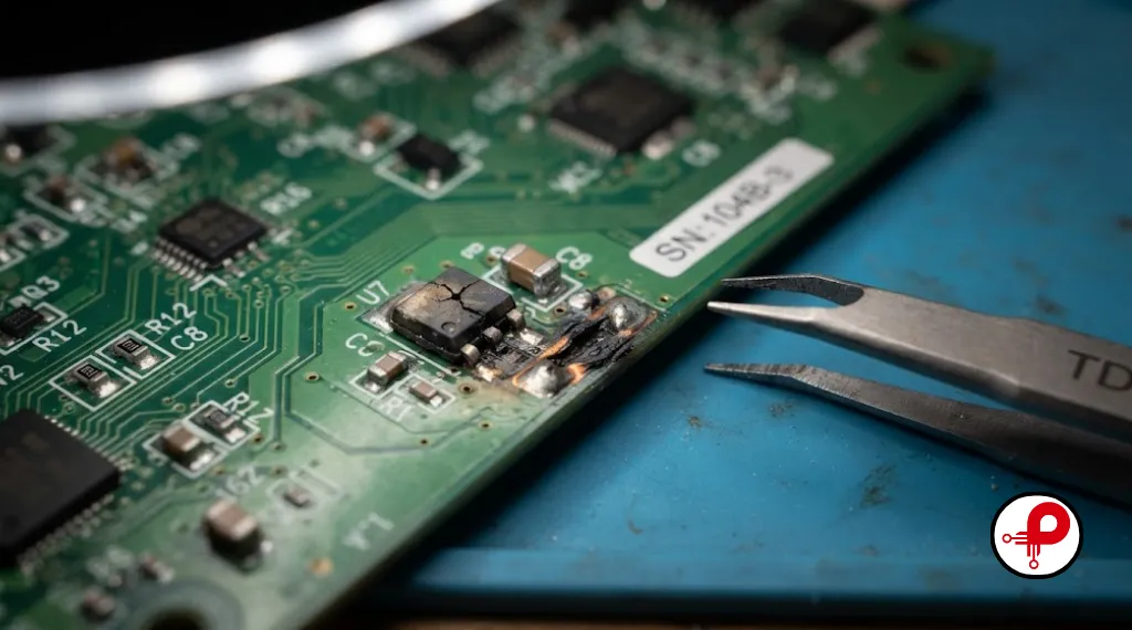
After years of reviewing hardware projects, the same mistakes show up again and again:
This premature step often forces expensive board re-spins later in the development cycle.
Testing should be built into the design input phase rather than treated as a secondary consideration.
Failure to account for potential EMC issues can add months to a project if a board fails on the first pass.
Selecting single-source components creates a fragile supply chain that is prone to disruption.
Copying a competitor’s circuit without understanding the underlying logic often reproduces bad design decisions along with the good ones.
Without a plan, teams are often left scrambling to understand certification requirements only after the design is already frozen.
How to Choose a Medical Device Development Partner
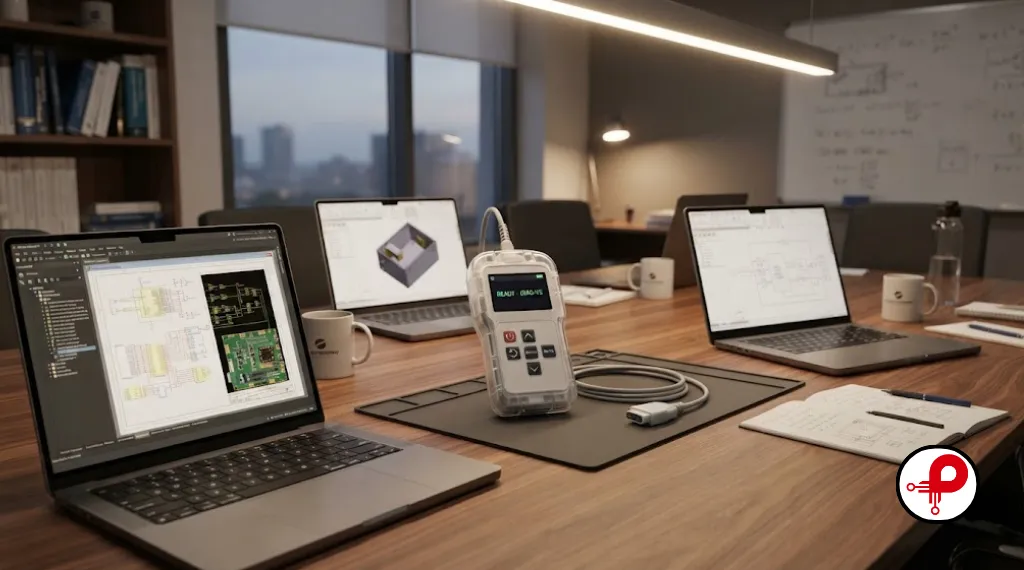
If you are evaluating medical device development services, look past the sales pitch and check for these signals:
- A documented quality management process, ideally ISO 13485 aligned, even if not yet certified
- Engineers who can speak fluently about design controls, not just circuit theory
- A track record of PCB design, firmware, and mechanical work under one roof, or a tightly coordinated network of specialists
- Willingness to discuss risk management and regulatory strategy before writing a single line of code
- Transparent communication about timelines, since realistic medical device development is measured in months and years, not weeks
Ask for references from projects that reached a regulatory milestone, not just a working prototype. A polished demo is not the same as a design history file that survives an FDA audit.
FAQ
1. What is Design for Manufacturing and Assembly (DFMA)?
↑2. How do I apply DFMA guidelines to my product?
↓3. What is the difference between DFM, DFA, and DFMA?
↓4. What are the main benefits of DFMA?
↓5. What are the most common DFMA mistakes?
↓6. Does DFMA apply to PCB and electronics design?
↓7. When should a DFMA review be performed?
↓8. Which industries benefit the most from DFMA?
↓A Real-World Example of Medical Device Development in Action
Consider a fictional but realistic scenario based on patterns I have seen repeatedly across wearable diagnostic projects. A small team sets out to build a wearable medical device that monitors a physiological signal continuously and alerts a caregiver through a companion app.
In the needs assessment stage, the team interviews clinicians and patients to understand what “useful” actually means in daily life, not just in a lab setting. That research becomes a design input document specifying battery life, skin contact requirements, and alert latency.
During architecture and prototyping, the team validates the sensor with an off-the-shelf development board before committing to a custom PCB design, following the same logic covered in our IoT prototyping guide referenced earlier. Once the sensor performance is confirmed, the team moves to a custom PCB, carefully planning stack-up and grounding to keep analog sensor traces isolated from the Bluetooth radio, a lesson learned the hard way on an earlier project where EMI from the radio corrupted sensor readings.
Risk analysis under ISO 14971 identifies a critical failure mode: if the wireless link drops, the caregiver should still be alerted locally rather than silently losing the connection. That single risk finding changes the firmware architecture, adding a local alarm state that does not depend on connectivity.
Verification testing confirms the device meets its design inputs across temperature, humidity, and battery conditions. Validation testing with real users in the intended environment confirms the alert is noticed reliably. With that evidence in hand, the team compiles a 510(k) submission, referencing electrical safety testing to IEC 60601 and cybersecurity documentation covering the companion app’s data handling.
Only after clearance does the team move to production tooling, transferring the design to a contract manufacturer for PCB assembly and enclosure molding, with incoming inspection procedures in place for every batch of sensors. This sequence, needs first, architecture second, prototyping third, risk and verification fourth, regulatory fifth, manufacturing last, is the pattern behind almost every medical device that reaches the market without a costly redesign.
Building a Realistic Budget and Timeline
Founders frequently underestimate both cost and schedule for medical device development, largely because consumer electronics benchmarks do not apply. A rough planning framework looks like this for a moderate complexity, connected Class II device:
- Concept, research, and design inputs: four to eight weeks
- Architecture, prototyping, and proof of concept: two to four months
- Detailed design, including PCB design and firmware: three to six months
- Verification, validation, and usability testing: two to four months
- Regulatory submission and review: three to nine months, depending on the pathway and FDA queue times
- Manufacturing transfer and pilot production: two to three months
Add contingency for at least one design iteration after verification testing surfaces an unexpected issue, because it almost always does. Teams that budget for a single perfect pass through the medical device development lifecycle are the ones most likely to blow their runway.
Final Thoughts
Medical device development rewards teams that respect the process rather than rush it. The companies that reach the market fastest, and stay there, are the ones that treat medical device design, prototyping, PCB engineering, risk management, and regulatory strategy as one connected discipline rather than separate boxes to check. Get the electronic hardware design right, document your risk decisions as you make them, and choose partners who understand both the engineering and the regulatory weight behind every component you select.
If you are starting a new medical device project and want a second set of eyes on your architecture, PCB layout, or regulatory roadmap, our engineering team works across the full medical device development lifecycle, from early proof of concept through production scaling.