










I have spent more than eight years designing industrial control boards, and RS485 is the interface I reach for whenever a project needs long cable runs, multiple nodes, and real noise immunity. It is not glamorous compared to Ethernet or wireless, but it works in factories, elevators, solar farms, and building automation systems where other protocols quietly fail. This guide walks through RS485 hardware circuit design the way I actually approach it on the bench, from transceiver selection to termination, biasing, PCB layout, and the mistakes that cause field returns.
Quick answer: A reliable RS485 circuit needs a differential transceiver (such as MAX485 or SN65HVD family devices) connected to a UART, a 120 ohm termination resistor at each end of the bus, failsafe biasing resistors to hold the line in a known idle state, transient protection near the connector, and controlled impedance differential pair routing on the PCB.
What Is RS485 and Why Engineers Still Choose It
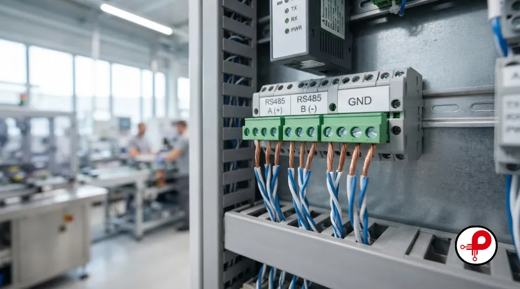
RS485, formally EIA/TIA485A, is a differential balanced serial standard built for multi-drop industrial communication circuits. Instead of one signal wire referenced to ground like RS232, RS485 uses two wires, commonly called A and B, that carry a mirrored signal. The receiver only cares about the voltage difference between the two lines, so common mode noise picked up along the cable cancels out.
That single property is why RS485 hardware circuit design remains dominant in factory automation, building management, solar inverters, HVAC controllers, and metering systems. A properly designed RS485 communication circuit can run reliably over 1200 meters at low data rates, support up to 32 standard unit loads on one bus, and shrug off electrically noisy environments that would destroy an RS232 link within meters.
When I explain this to junior engineers, I frame it around three advantages over the alternatives. It tolerates long cable runs better than USB or RS232. It supports multi-drop communication so many devices share one pair of wires, unlike point-to-point interfaces. It is inexpensive, since transceivers cost well under a dollar in volume and the protocol needs no licensing.
That said, RS485 is not automatically robust. I have debugged more field failures caused by missing termination or biasing than by any component defect. The electrical theory is simple, but getting the RS485 circuit schematic, PCB layout, and cabling right at the same time is where projects succeed or stall.
If you are scoping a new product around this interface, it helps to plan the whole electronic product design workflow early, since the choice of transceiver, isolation, and connector affects enclosure, certification, and cost targets long before the first prototype is built.
RS485 Differential Signaling Fundamentals
Understanding differential signaling is the foundation of every RS485 interface circuit decision that follows. A driver outputs a voltage difference of at least 1.5V across a 54 ohm load, and a compliant receiver must correctly detect any differential voltage above 200mV as a logic one and below negative 200mV as a logic zero. Anything between those thresholds is undefined, which is exactly the gap that termination and biasing exist to manage.
RS485 Signal Integrity & Transmission Principles
Common Mode Noise Rejection
RS485 uses differential signaling, so the receiver detects only the voltage difference between lines A and B. Noise that affects both wires equally (common mode noise) is automatically rejected, improving communication reliability.
Importance of Twisted Pair Cable
Twisted pair cable ensures both conductors experience nearly the same electromagnetic interference. This helps maintain the noise cancellation capability of RS485, making it ideal for industrial environments.
Common Mode Voltage Range
RS485 supports a common mode voltage range of -7V to +12V, allowing reliable communication even when connected devices have different ground potentials. Transceivers with a narrower range may experience communication failures.
Transmission Line Effects & Signal Reflections
At longer cable lengths or higher data rates, the cable behaves like a transmission line. Without proper termination, impedance mismatches create signal reflections that can distort data and cause intermittent communication errors.
RS485 Transceiver Circuit Design
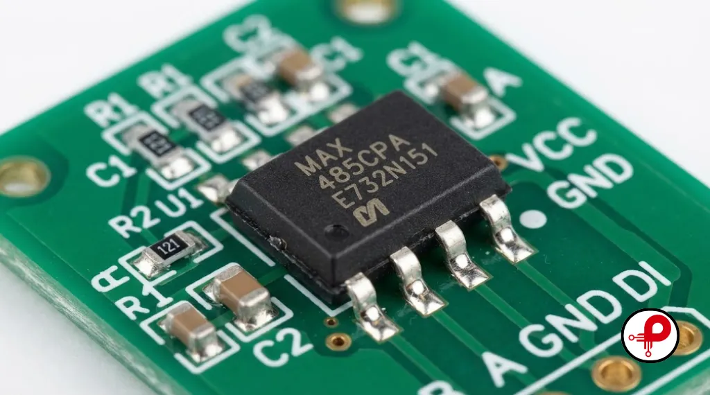
The transceiver is the heart of any RS485 circuit design. It converts single ended logic level signals from a microcontroller UART into the differential A and B signals the bus expects, and it does the reverse on receive. Two chip families dominate real designs I see in the field: the classic MAX485 transceiver from Analog Devices, and the SN65HVD family from Texas Instruments.
MAX485 Transceiver Circuit Basics
The MAX485 is a half duplex device in an 8 pin package, running from a single 5V supply, supporting up to 2.5Mbps with unlimited slew rate drivers. Pins RO and DI connect to the microcontroller UART, while DE and RE control direction. Tying DE and RE together and driving them from a single GPIO is the most common half duplex RS485 circuit pattern, letting firmware switch instantly between transmit and receive.
SN65HVD and Modern Transceiver Options
The SN65HVD485E transceiver from Texas Instruments supports both 3.3V and 5V operation, integrates surge and ESD protection, and allows up to 64 nodes on a single bus due to its low input current design. Newer generations, such as the 1/8 unit load parts, allow as many as 256 transceivers to share one bus, which matters in large multi-drop communication networks like building automation risers.
| Transceiver Feature | MAX485 Style | SN65HVD Style | Why It Matters |
|---|---|---|---|
| Supply voltage | 5V only | 3.3V and 5V options | Matches modern low power MCUs |
| Max data rate | 2.5 Mbps | Up to 10 Mbps on some variants | Higher throughput for sensor networks |
| Unit load rating | 1 UL, 32 nodes max | 1/8 UL, up to 256 nodes | Larger industrial RS485 design networks |
| Built in ESD protection | Basic | Up to 16kV HBM on robust parts | Fewer external protection parts |
| Failsafe biasing | External resistors needed | Often integrated | Simplifies RS485 wiring diagram |
Choosing between these depends on node count, required data rate, and whether the product needs 3.3V compatibility for battery operation. For a new industrial product, I typically start with the electronic component selection guidelines our team uses, which weight long term availability and ESD robustness as heavily as price.
RS485 Hardware Circuit Design for a Complete Node
A complete RS485 hardware circuit design has four functional blocks: the microcontroller UART, the transceiver, the termination and biasing network, and the protection stage at the connector. Getting the interaction between these blocks right is what separates a design that passes bench testing from one that survives years on a factory floor.
UART to RS485 Interfacing
Connecting UART to RS485 requires only four signal connections in a half duplex design. TX from the microcontroller goes to DI on the transceiver, RX comes from RO, and a single GPIO drives DE and RE together to control transmit versus receive direction. Firmware must assert DE before the first byte and release it only after the last stop bit has fully shifted out, otherwise the final byte gets clipped on the bus, a bug I have chased more than once.
Power Supply and Decoupling
Each transceiver supply pin needs a 100nF ceramic decoupling capacitor placed as close to the pin as physically possible, a practice confirmed across nearly every transceiver datasheet I have reviewed. A bulk capacitor of 1 to 10 microfarads near the regulator output further stabilizes the rail during transmit current spikes, which can be significant when driving a heavily loaded RS485 bus design with dozens of nodes.
Direction Control Timing
If your microcontroller UART does not support automatic direction control, add a small RC delay or use the UART’s transmit complete interrupt rather than the transmit buffer empty interrupt to toggle DE. This single detail resolves a large share of Modbus RTU timing complaints I see from teams building their first RS485 interface circuit.
For teams still selecting a microcontroller platform for a new industrial product, our ESP32 selection guide covers which variants have hardware RS485 direction control support built into their UART peripherals, which removes an entire category of firmware bugs.
RS485 Circuit Schematic Walkthrough
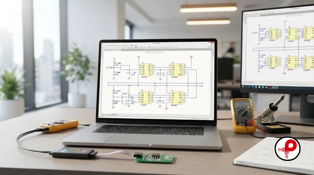
Reading an RS485 circuit schematic becomes intuitive once you know what each block is doing. Start at the microcontroller UART pins, follow TX and RX to the transceiver’s DI and RO pins, note the DE and RE control line, then trace outward to the A and B differential pair, the termination resistor, the biasing network, and finally the connector with its protection components.
A typical half duplex node schematic includes: the transceiver IC, a 100nF decoupling capacitor at VCC, a series ferrite bead or small resistor on DE and RE if the design needs extra noise immunity, a 120 ohm termination resistor placed only at bus end nodes, a pair of biasing resistors (commonly 560 ohm to 4.7k depending on node count), and a TVS diode array between A, B, and ground at the connector.
I always annotate my schematics with the expected differential voltage at idle and during transmission, because it gives whoever debugs the board later an instant reference point on the oscilloscope. This habit alone has cut troubleshooting time on returned boards significantly, and it is a detail worth building into your standard circuit board design rules documentation.
RS485 Termination Resistor and Biasing Resistors
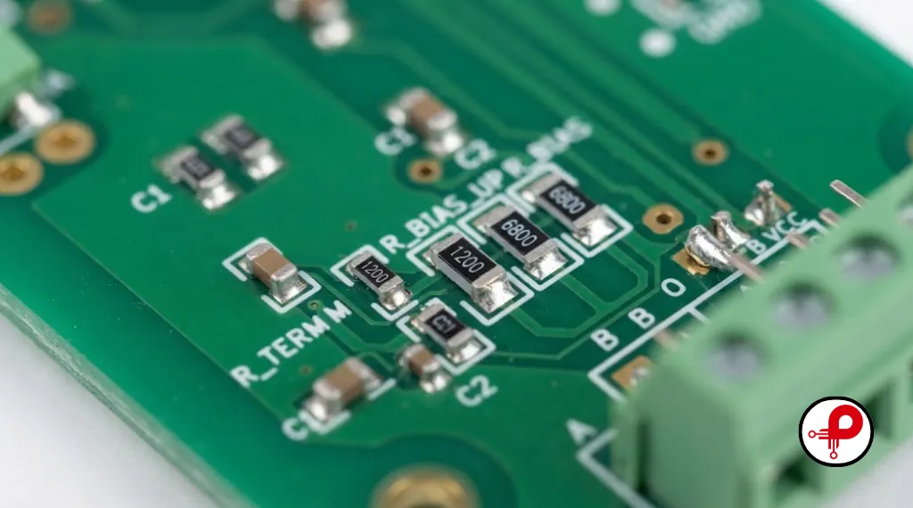
Termination and biasing are the two concepts most often implemented incorrectly, and they are different problems even though they interact. Termination prevents signal reflections; biasing prevents an undefined idle state. Both matter, but for different reasons, and confusing them leads to networks that work on the bench and fail once installed with real cable lengths.
RS485 Termination Resistor Placement
A 120 ohm resistor matching the cable’s characteristic impedance should be installed at each physical end of the bus, and only at the ends, never at intermediate nodes. Two termination resistors in parallel present a 60 ohm load to the driver, which is within spec for standard transceivers rated to drive 54 ohms. Adding more than two terminations overloads the driver and weakens the signal for every node on the bus.
As detailed in TI’s RS485/RS422 termination guidance, termination becomes necessary once cable length and data rate combine to make reflection settling time a meaningful fraction of the bit period. Short, slow links can often skip termination entirely, but any industrial RS485 design running above roughly 100kbps over more than a few meters should include it as standard practice.
RS485 Biasing Resistors and Failsafe Design
Biasing resistors, typically one pull up resistor from the A line to VCC and one pull down resistor from the B line to ground, force a known differential voltage when no driver on the bus is active. Without biasing, an idle bus can float into the undefined region between negative and positive 200mV, and the receiver may output random noise that firmware interprets as corrupted data.
STMicroelectronics’ fail-safe biasing application note walks through the resistor divider math in detail. As a working rule I use on new industrial RS485 design projects: with 120 ohm terminations at both ends giving a 60 ohm equivalent load, a pair of 560 ohm biasing resistors typically produces around 200 to 250mV of idle differential voltage from a 5V supply, comfortably above the receiver threshold.
| Bus Configuration | Termination | Biasing Resistor Value (approx) | Idle Differential Voltage |
|---|---|---|---|
| Short bus, low data rate, few nodes | Optional | 4.7k pull up / pull down | Marginal, verify with scope |
| Standard industrial bus, both ends terminated | 120 ohm at each end | 560 ohm to 1k pull up / pull down | 200 to 300 mV |
| Long bus, many nodes, high reliability | 120 ohm at each end | Calculated per unit load budget | 200 mV minimum guaranteed |
A single biasing network on the entire bus, placed at one node or at a central hub, is generally preferred over multiple competing biasing networks at several nodes, which can fight each other and reduce the effective idle voltage. For deeper theory on the underlying transmission line behavior, EDN’s explanation of passive fail-safe biasing is one of the clearest references available.
RS485 PCB Design and Layout Best Practices

RS485 PCB design determines whether a theoretically correct schematic actually performs in the field. Differential pair routing, grounding, and component placement all influence signal integrity and EMC compliance more than most engineers expect from what looks like a slow, simple interface.
Differential Pair Routing
Route the A and B traces as a matched differential pair with consistent spacing along their entire length, targeting roughly 120 ohm differential impedance to match the cable. Keep the pair length matched within a few millimeters, avoid routing them on separate layers unless necessary, and never split the pair around a component without a very short, symmetrical detour.
Grounding and Return Path
PCB grounding directly affects EMI performance in RS485 circuits. Provide a solid, unbroken ground plane beneath the differential pair so the return current has a continuous low impedance path. Avoid routing the A and B traces across a split in the ground or power plane, since that discontinuity is a classic source of radiated emissions and susceptibility to external noise.
Component Placement for EMI Reduction
Place the transceiver close to the connector to minimize the length of unprotected trace exposed to the harsh outside environment, and place protection components such as TVS diodes as close to the connector pins as physically possible. According to MaxLinear’s RS232 and RS485 PCB layout application note, decoupling capacitors placed close to supply pins and avoidance of long loop traces are two of the highest impact layout habits for both signal integrity and EMC design.
If your product also needs a wireless radio alongside RS485, keep the transceiver and its differential pair well separated from antenna structures. Our notes on 2.4 GHz PCB antenna design cover keep out zones that apply equally well when a design mixes RS485 wired communication with a Wi-Fi or Bluetooth gateway on the same board.
Comparing PCB design intent against the final layout execution is where many boards go wrong. If your team is unclear on where design responsibility ends and layout execution begins, it is worth reviewing the distinction between PCB design versus PCB layout before finalizing stack up and routing rules for an RS485 heavy board.
RS485 Wiring, Bus Topology, and Network Design
RS485 network design is not only a PCB and schematic problem, it is also a cabling and topology problem. A perfectly designed node can still suffer from unreliable communication if the network wiring diagram uses the wrong topology.
Daisy Chain Versus Star Topology
RS485 bus design assumes a linear daisy chain topology, where each node connects to the main trunk cable with the shortest possible stub. Star topologies, where multiple branches radiate from a central point, introduce impedance discontinuities at every branch point and are a leading cause of reflection related errors, even though they are tempting from a wiring convenience standpoint.
| Topology | Reliability | Wiring Complexity | Recommended Use |
|---|---|---|---|
| Daisy chain, both ends terminated | High | Moderate, requires planning | Standard industrial RS485 design |
| Star with short stubs under 0.3m | Moderate | Simple to wire | Small networks, low data rate |
| Star with long branch stubs | Low | Simple to wire | Not recommended |
Cable Selection and Multi-Drop Communication
Use shielded twisted pair cable with a characteristic impedance close to 120 ohms for any serious industrial communication circuit. The shield should be grounded at one end only in most installations to avoid ground loop currents, though some site standards require both ends bonded through a capacitor. Multi-drop communication networks with more than a handful of nodes benefit from labeling each drop clearly during installation, since troubleshooting a live factory bus without documentation is one of the least enjoyable tasks in industrial electronics.
For products destined for harsh or regulated environments, cabling and connector choices often intersect with certification requirements. It is worth reviewing how to certify an electronic product early, since EMC test failures traced back to RS485 cabling are common and expensive to fix late in a program.
Protection Circuits: ESD, TVS, and Isolation
Field wiring is the most abused part of any RS485 hardware circuit design. Installers miswire connectors, lightning induces surges on long cable runs, and static discharge from personnel is a daily occurrence around industrial equipment. Robust protection circuitry is not optional for products that will leave a lab bench.
RS485 Hardware Protection & Environmental Hardening
TVS Diode Protection
Place a bidirectional TVS diode array between the A line and ground, and between the B line and ground, right at the connector. This clamps transient overvoltage events before they reach the transceiver. Devices like the SN65HVD1785 include internal transient protection rated to withstand high voltage HBM strikes, but as TI’s own support engineers note in field discussions, additional external TVS protection is still recommended for connections exposed to accidental mis-wiring or long outdoor cable runs.
ESD Protection at the Connector
Even indoor equipment accumulates electrostatic charge on connector housings. A transceiver rated for 8kV to 16kV ESD protection, combined with board level TVS diodes, gives enough margin for most industrial automation and building management installations without adding meaningful cost to the bill of materials.
Isolation Circuits for High Noise Environments
In environments with large motors, variable frequency drives, or significant ground potential differences between nodes, a digital isolator combined with an isolated DC to DC converter creates a fully isolated RS485 interface circuit. This breaks the ground loop entirely rather than just clamping transients, and it is the approach I recommend whenever a node sits near high power switching equipment. It adds cost and board area, so weigh it against the actual noise environment rather than applying it by default.
Industrial RS485 Design and Protocol Considerations

Most RS485 hardware circuit design work exists to carry a higher layer protocol, and Modbus RTU is by far the most common in industrial automation. Understanding how the protocol uses the physical layer clarifies several hardware decisions.
Modbus RTU and PLC Communication
Modbus RTU over RS485 uses precise inter-character and inter-frame timing gaps to distinguish message boundaries, which is why direction control timing in the DE and RE circuit matters so much. A PLC communication network running Modbus RTU typically operates at 9600 to 115200 baud, well within the comfortable range for both MAX485 style and SN65HVD style transceivers.
Half Duplex Versus Full Duplex RS485
Half duplex communication uses a single twisted pair and time division between transmit and receive, which is simpler to wire and dominates real installations. Full duplex RS485 uses two separate pairs, one for each direction, allowing simultaneous transmit and receive, but it doubles cabling cost and is mostly seen in point to point links or systems needing continuous bidirectional throughput.
Embedded Systems Integration
Integrating RS485 into embedded systems firmware means handling direction control, framing, CRC checks for Modbus, and often a state machine for master or slave roles. Getting this right the first time saves significant rework, which is why we typically fold RS485 firmware validation into the broader embedded systems development and hardware bring up process rather than treating it as an afterthought once the board arrives.
Product categories beyond factory floors are adopting RS485 as well. Medical equipment interconnects, wearable device charging docks, and even research instrumentation use it for its noise immunity, though these applications bring their own certification path. Anyone building connected medical hardware should review medical device development requirements in parallel with the communication circuit design, and teams working on connected wearables can find relevant grounding and interference notes in our wearable technology development resources.
Common Mistakes, Troubleshooting, and Checklist
After years of reviewing other engineers’ RS485 designs, the same handful of mistakes show up repeatedly. Missing or duplicated termination resistors top the list, followed closely by biasing networks fighting each other because more than one node has its own bias resistors enabled. Star topology with long stubs is another frequent culprit, along with DE and RE toggled too early, clipping the last transmitted byte.
RS485 Network Troubleshooting & Validation Checklist
Verification Steps
Best Practices Summary
Keep stub lengths under roughly 30cm wherever possible in a daisy chain topology.
Use one biasing network per bus, not one per node.
Add TVS protection at every field accessible connector, not just the “main” one.
Document expected idle and active differential voltages directly on the schematic for future troubleshooting.
Prototype the full cable run length during validation testing rather than relying only on a bench setup with a one meter cable, since reflection and attenuation effects only appear at realistic distances.
Before committing a new industrial product to production, running the communication circuit through a full PCB testing and inspection pass under realistic cable lengths catches these issues while they are still cheap to fix. Many hardware programs also stumble on process and planning rather than pure electrical design, which is worth keeping in mind alongside the technical checklist above by reviewing common reasons why hardware startups fail.
Teams building their first industrial RS485 design product, or scaling from a single prototype to a manufacturable product line, often benefit from structured industrial product design engineering support and a clear rapid prototyping and IoT prototype plan to validate the communication circuit under real field conditions before committing to tooling. Reviewing PCB layout best practices alongside this guide will round out the physical layer implementation details specific to your board’s stack up and component library.
Frequently Asked Questions
1. What is the maximum cable length for an RS485 circuit?
↑2. Do I always need termination resistors on an RS485 bus?
↓3. What is the difference between RS485 and RS422?
↓4. Why does my RS485 network work on the bench but fail once installed?
↓5. How many devices can share one RS485 bus?
↓6. Why do I need biasing resistors if my transceiver has failsafe built in?
↓7. What causes intermittent Modbus RTU communication errors?
↓8. Should I use star or daisy chain topology for RS485?
↓9. How do I convert UART to RS485?
↓10. What is the best transceiver for a new industrial RS485 design?
↓Key takeaways from this guide: match your transceiver to your voltage rail and node count requirements, terminate only at the physical bus ends with 120 ohm resistors, add a single well calculated biasing network rather than multiple competing ones, route the differential pair over an unbroken ground plane, and protect every field connector with TVS diodes before it ever reaches an installation site. These five habits resolve the overwhelming majority of RS485 field failures I have diagnosed over the years.
If you are moving from schematic to a manufacturable industrial product, our team can support the complete path from RS485 circuit design through layout, prototyping, and certification. Reach out to discuss your project and get a design review that catches termination, biasing, and layout issues before they reach the field.