



You have an Arduino Uno R3, a few jumper wires and a sensor ready to connect. The board has rows of pins along its edges, but which one should you use? Choosing the wrong connection can cause a sensor to give unexpected readings, interrupt serial communication or damage a component.
The Arduino Uno pinout helps you identify every connection before you start wiring. It shows the digital and analog pins, power connections and communication interfaces. Once you understand the layout, connecting a display, temperature sensor, motor driver or other module becomes much easier.
This guide focuses on the Arduino Uno R3 pinout, with practical wiring examples, code and electrical specifications. It also explains the differences between the R3 and Uno R4 WiFi, since their internal hardware is different.
What Is an Arduino Uno Pinout?
A pinout is a reference diagram that identifies the pins on an electronic board and explains what each one does. On the Arduino Uno R3, these connections allow the ATmega328P microcontroller to communicate with sensors, displays, buttons, motors and other electronic components.
The board has 14 digital input/output pins, six analog inputs and several power connections. Some pins have additional functions. D0 and D1 handle serial communication, while A4 and A5 provide the standard I²C connection.
You control these pins through the Arduino IDE using functions such as pinMode(), digitalWrite(), digitalRead() and analogRead(). The pinout tells you where to connect the hardware before writing your sketch.
Arduino Uno R3 Pinout Diagram
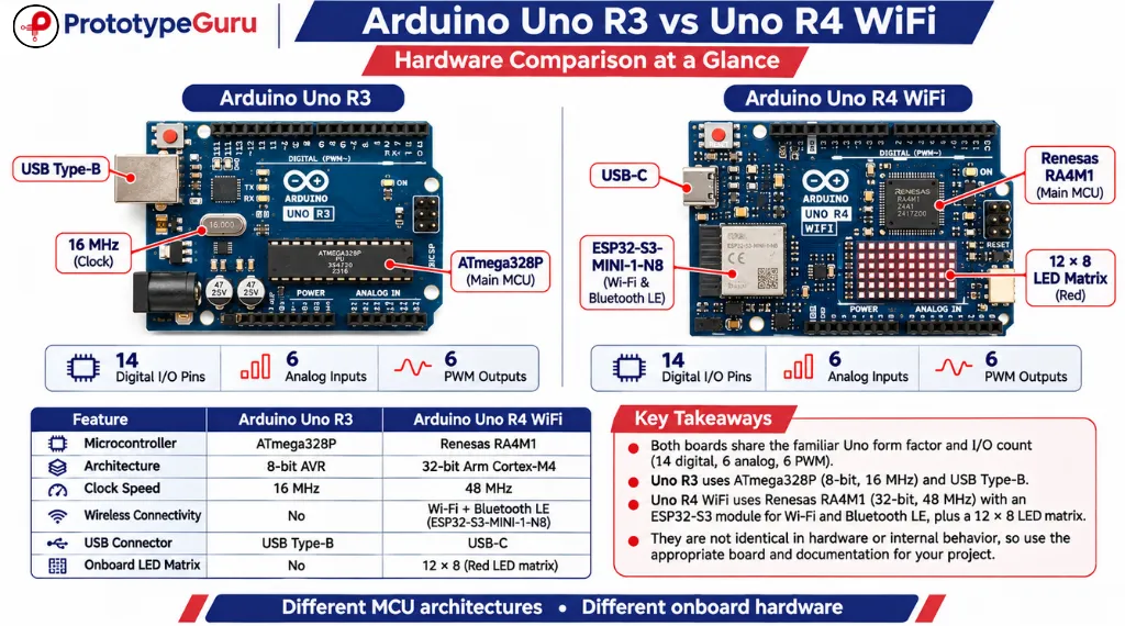
The diagram should match the board’s actual orientation. Use the USB Type-B connector and DC power jack to identify the correct viewing direction. This matters when matching a physical pin to a wiring diagram.
For an exact reference, Arduino provides an official pinout PDF:
Download the official Arduino Uno R3 pinout diagram.
Arduino Uno R3 Specifications
The Uno R3 uses the ATmega328P microcontroller and runs at a 16 MHz clock speed. Its memory and I/O resources are suitable for many small electronics projects, including sensor monitoring, basic automation and control systems.
| Specification | Arduino Uno R3 |
|---|---|
| Microcontroller | ATmega328P |
| Operating voltage | 5V |
| Recommended input voltage | 7-12V |
| Input voltage limit | 6-20V |
| Digital I/O pins | 14 |
| Analog input pins | 6 |
| PWM pins | 6 |
| ADC resolution | 10-bit |
| Clock speed | 16 MHz |
| Flash memory | 32 KB |
| SRAM | 2 KB |
| EEPROM | 1 KB |
| Recommended current per I/O pin | 20 mA |
| 3.3V output current limit | 50 mA |
These specifications describe the standard Uno R3. Some compatible boards use different USB-to-serial chips or small layout changes, so check the manufacturer’s documentation if your board is a clone.
Arduino Uno Digital Pins D0 to D13
The digital header contains 14 pins, labelled D0 through D13. Each pin can work as an input or output.
As an input, a pin reads a HIGH or LOW signal. A push button, for example, can connect to an input so the Arduino detects when it is pressed. As an output, the pin can control an LED or send a signal to a transistor or driver module.
Some digital pins also support dedicated hardware functions.
| Pin | Digital function | Additional function |
|---|---|---|
| D0 | Input/output | UART RX |
| D1 | Input/output | UART TX |
| D2 | Input/output | External interrupt INT0 |
| D3 | Input/output | PWM, external interrupt INT1 |
| D4 | Input/output | General-purpose I/O |
| D5 | Input/output | PWM |
| D6 | Input/output | PWM |
| D7 | Input/output | General-purpose I/O |
| D8 | Input/output | General-purpose I/O |
| D9 | Input/output | PWM |
| D10 | Input/output | PWM, SPI SS |
| D11 | Input/output | PWM, SPI MOSI |
| D12 | Input/output | SPI MISO |
| D13 | Input/output | SPI SCK, onboard LED |
The extra functions matter when a project uses several modules. Suppose you connect an SPI display and an LED. The display needs D11, D12 and D13 for communication, so assigning those pins to unrelated hardware could interfere with the display.
Digital Pin Example: Blinking an LED
Connect an LED in series with a suitable current-limiting resistor between D7 and GND. The longer LED leg is usually the anode, which connects towards the resistor and Arduino output.
const int ledPin = 7;

void setup() {
  pinMode(ledPin, OUTPUT);
}

void loop() {
  digitalWrite(ledPin, HIGH);
  delay(1000);

  digitalWrite(ledPin, LOW);
  delay(1000);
}
The LED stays on for one second, switches off for one second and repeats the cycle. You can change the pin number in the sketch if you move the wire to another available digital pin.
For a push button wired between an input pin and GND, INPUT_PULLUP is useful. The input reads HIGH while the button is released and LOW while it is pressed. The internal pull-up resistor keeps the input from floating when the button is open.
Read our guide to pull-up resistors for a closer look at how this works.
Arduino Uno Analog Pins A0 to A5
The six analog input pins are labelled A0, A1, A2, A3, A4 and A5. They measure changing voltage levels from sensors and other analog circuits.
A potentiometer is a simple example. Its output voltage changes as you turn the shaft, and the Arduino reads that voltage through an analog input.
The ATmega328P has a 10-bit analog-to-digital converter (ADC). With the default 5V reference, it converts the input into a reading from 0 to 1023.
| Analog pin | Main function | Additional function |
|---|---|---|
| A0 | Analog input | Digital I/O |
| A1 | Analog input | Digital I/O |
| A2 | Analog input | Digital I/O |
| A3 | Analog input | Digital I/O |
| A4 | Analog input | I²C SDA, digital I/O |
| A5 | Analog input | I²C SCL, digital I/O |
For an approximate voltage calculation, use:
For example, a reading close to 512 represents approximately 2.5V when the reference is 5V.
The actual result depends on the reference voltage and electrical conditions in the circuit. Keep the analog input within the permitted voltage range.
Analog Sensor Example
Connect a sensor’s analog output to A0. Connect its supply and ground according to the sensor’s datasheet.
const int sensorPin = A0;

void setup() {
  Serial.begin(9600);
}

void loop() {
  int sensorValue = analogRead(sensorPin);

  Serial.println(sensorValue);
  delay(500);
}
Open the Serial Monitor and select 9600 baud. The reading will change as the sensor output voltage changes.
If you are testing with a potentiometer, connect its two outer terminals to 5V and GND, then connect the middle terminal to A0. Turning the shaft changes the voltage measured by the Arduino.
Arduino projects frequently combine analog sensors with digital control circuits. Our guide to analog and digital circuit design explains how these signal types behave.
Arduino Uno PWM Pins
PWM stands for Pulse Width Modulation. It controls the duty cycle of a digital signal, which can be used to adjust LED brightness or control a motor through a suitable driver.
The Uno R3 supports PWM on six digital pins:
D3, D5, D6, D9, D10 and D11.
Look for the ~ symbol beside these pins on the board. In the Arduino IDE, analogWrite() accepts a value from 0 to 255.
analogWrite() value | Approximate duty cycle |
|---|---|
| 0 | 0% |
| 64 | 25% |
| 128 | 50% |
| 192 | 75% |
| 255 | 100% |
A PWM output switches between LOW and HIGH. Changing the duty cycle controls the proportion of each cycle spent at HIGH.
PWM LED Example
Connect an LED and current-limiting resistor to D9 and GND.
const int ledPin = 9;

void setup() {
  pinMode(ledPin, OUTPUT);
}

void loop() {
  for (int brightness = 0; brightness <= 255; brightness++) {
    analogWrite(ledPin, brightness);
    delay(10);
  }

  for (int brightness = 255; brightness >= 0; brightness--) {
    analogWrite(ledPin, brightness);
    delay(10);
  }
}
The LED gradually brightens and then dims. Try changing ledPin to D5 or D6 to test another PWM output.
A motor needs a suitable driver circuit. Its current demand can exceed the rating of an Arduino pin, and the motor’s electrical noise can also affect the board.
If you’re working with a servo, see our practical guide to connecting an Arduino servo motor for wiring and control examples.
Arduino Uno Power Pins Explained
The power header contains connections for external power, regulated voltage, ground and reset. Each has a specific job.
| Pin | Function |
|---|---|
| VIN | External voltage input |
| 5V | Regulated 5V supply |
| 3.3V | 3.3V output |
| GND | Ground |
| RESET | Resets the microcontroller when pulled LOW |
| IOREF | Indicates the board’s I/O operating voltage |
| AREF | External analog reference input |
VIN
VIN is used to supply external power through the power header. For the Uno R3, the recommended input range is 7-12V.
The board can also receive power through its DC barrel jack. The voltage supplied through VIN or the barrel jack passes through the board’s power circuitry.
5V
The 5V pin provides the board’s regulated 5V supply. It can power suitable sensors and small modules, provided their combined current demand stays within the available power budget.
Be careful when applying an external supply to this pin. An incorrect voltage or conflicting power source can damage the board.
3.3V
The 3.3V pin supplies small modules that require 3.3V. Its maximum rated output current is 50mA.
Check the module’s datasheet before connecting it. Some devices require 3.3V power and 3.3V logic, while others include their own voltage regulation or level shifting.
GND
GND is the circuit’s common ground reference. When the Arduino communicates with an external sensor or module, their grounds usually need to be connected together so both devices share the same signal reference.
RESET
Pulling RESET LOW restarts the microcontroller. The reset button on the board performs the same basic function.
IOREF and AREF
IOREF indicates the Uno R3’s I/O operating voltage, which is 5V. Compatible shields can use this connection to identify the board’s logic level.
AREF is used as an external analog reference for the ADC. If you connect an external reference, configure it with analogReference(EXTERNAL). Follow the voltage limits in the ATmega328P documentation and avoid applying a voltage above the permitted range.
When choosing a supply for a larger project, read our guide to power supplies for embedded systems.
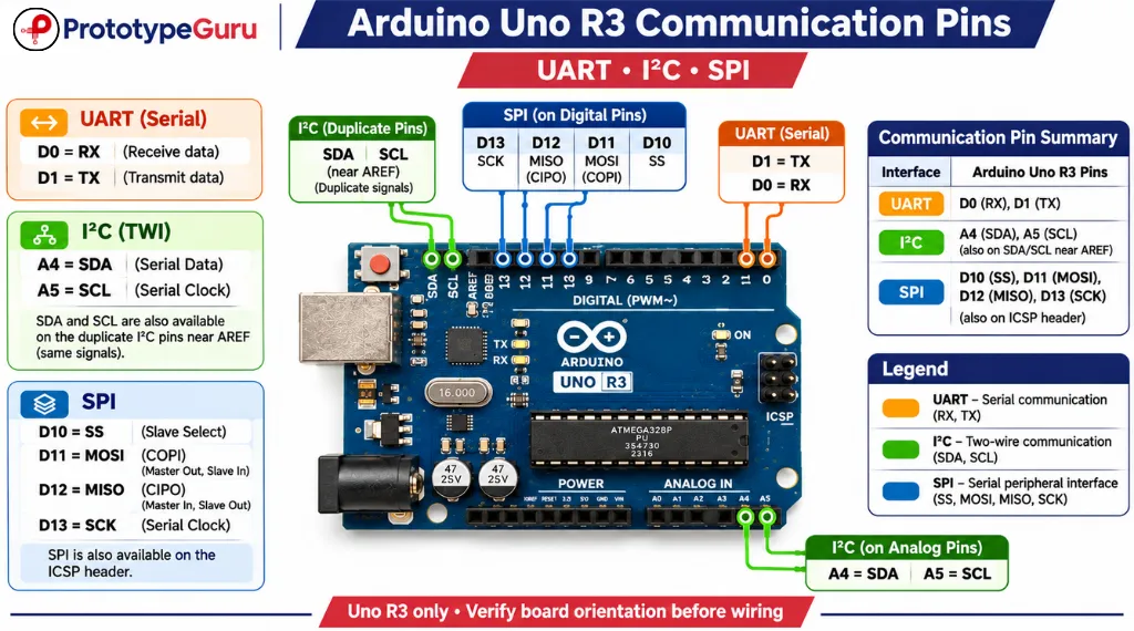
UART, I²C and SPI Pin Connections
The Uno R3 supports three widely used communication interfaces. Each one has its own pin assignments.
UART Serial Communication
UART provides serial communication between the Arduino and another device. The Uno R3 uses D0 and D1.
| Signal | Pin |
|---|---|
| RX | D0 |
| TX | D1 |
RX receives data, while TX transmits it. The Arduino IDE’s Serial object uses this hardware connection.
void setup() {
  Serial.begin(9600);
}

void loop() {
  Serial.println("Arduino Uno R3");
  delay(1000);
}
Open the Serial Monitor at 9600 baud to view the message.
One wiring detail can cause trouble here. D0 and D1 are also connected to the board’s USB-to-serial interface. An external device connected to these pins can interfere with sketch uploads or Serial Monitor communication.
I²C Communication
I²C uses two signal lines to communicate with compatible sensors, displays and other peripherals.
| Signal | Uno R3 pin |
|---|---|
| SDA | A4 |
| SCL | A5 |
SDA carries data and SCL carries the clock signal. Multiple I²C devices can share the same bus when they use suitable addresses and the wiring is correct.
The Uno R3 also exposes SDA and SCL on dedicated connections near AREF. These are electrically connected to A4 and A5.
For example, an I²C LCD adapter can connect to the Uno using four connections: SDA, SCL, VCC and GND. Check the adapter’s voltage requirements before powering it.
SPI Communication
SPI is a synchronous communication interface used by devices such as SD card modules, displays and radio modules.
| SPI signal | Uno R3 pin |
|---|---|
| SS | D10 |
| MOSI | D11 |
| MISO | D12 |
| SCK | D13 |
MOSI carries data from the Arduino to the peripheral. MISO carries data back to the Arduino, and SCK provides the clock signal. SS selects the peripheral.
The SPI signals are also available on the six-pin ICSP header. This is useful for compatible shields and programmers that connect through that header.
If you want to understand the differences in wiring and data transfer, read our guide to I²C vs SPI vs UART communication protocols.
ICSP Header and External Interrupt Pins
The Uno R3 has a six-pin ICSP header. ICSP stands for In-Circuit Serial Programming. It provides access to programming and SPI connections on the microcontroller.
The header carries these signals:
| ICSP signal | Function |
|---|---|
| MISO | SPI data from peripheral |
| VCC | Supply voltage |
| SCK | SPI clock |
| MOSI | SPI data to peripheral |
| RESET | Microcontroller reset |
| GND | Ground |
Use the official pinout diagram to check the header orientation before connecting a programmer. The physical position of pin 1 matters, so do not assume the connector can be reversed safely.
The Uno R3 also has two external interrupt pins.
| Pin | Interrupt |
|---|---|
| D2 | INT0 |
| D3 | INT1 |
An external interrupt lets the microcontroller respond to a change in an input signal without waiting for the next normal pass through loop(). This is useful for encoder pulses, pulse counting and other time-sensitive input events.
Arduino Uno R3 Electrical Limits
Before connecting a component, check how much voltage and current it needs. A pinout diagram tells you where a connection goes, while the electrical ratings tell you whether the connection is safe.
The recommended operating current for an individual I/O pin is 20mA. Treat this as the working limit for normal circuit design. The 3.3V output has a maximum rated current of 50mA.
A few practical precautions:
- Add a suitable resistor when connecting an LED.
- Use a motor driver or transistor circuit for motors.
- Check the voltage requirements of every sensor and module.
- Connect grounds when devices share signal connections.
- Keep the current drawn from the 5V and 3.3V supplies within their limits.
- Check the pin assignments before installing a shield.
A relay coil, motor or high-power LED can draw far more current than a microcontroller pin can supply. Use a suitable driver and provide an appropriate supply for the load.
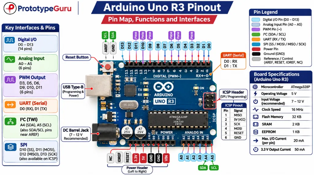
Arduino Uno R3 vs Uno R4 WiFi
The Uno R4 WiFi uses the familiar Uno board format, but its internal hardware is different from the R3. The R3 uses an ATmega328P microcontroller, while the R4 WiFi uses a 32-bit Renesas RA4M1 and includes an ESP32-S3 module for wireless connectivity.
| Feature | Uno R3 | Uno R4 WiFi |
|---|---|---|
| Main microcontroller | ATmega328P | Renesas RA4M1 |
| Architecture | 8-bit AVR | 32-bit Arm Cortex-M4 |
| Clock speed | 16 MHz | 48 MHz |
| Flash memory | 32 KB | 256 KB |
| SRAM | 2 KB | 32 KB |
| Operating voltage | 5V | 5V for RA4M1 GPIO |
| Wireless connectivity | No built-in Wi-Fi or Bluetooth | Wi-Fi and Bluetooth LE |
| USB connector | USB Type-B | USB-C |
| Built-in LED matrix | No | 12 × 8 LED matrix |
The R4 WiFi also includes a DAC, CAN bus support and a Qwiic connector. Its ESP32-S3 module handles wireless connectivity, while the RA4M1 runs the main application.
The R4 WiFi has its own pinout and electrical details. Use its official documentation when wiring that board.
Read the Arduino Uno Q guide to learn about another board in the Uno family.
Common Arduino Uno Pinout Mistakes
A few wiring mistakes can cause confusing behaviour, especially when a project combines several modules.
Using D0 and D1 without checking serial communication
These pins handle UART communication and connect to the USB-to-serial interface. An external module can interfere with uploading sketches or receiving Serial Monitor messages.
Confusing analog input with PWM output
A0 to A5 measure analog voltage. The analogWrite() function uses PWM on supported digital pins. The Uno R3 does not provide a true analog voltage output.
Connecting a motor directly to an Arduino pin
A motor can draw more current than the microcontroller can supply. Use a motor driver or suitable transistor circuit, with an appropriate power supply.
Applying 5V to a 3.3V-only module
Some modules cannot tolerate 5V logic. Check the datasheet and use a suitable logic-level converter when required.
Reversing SDA and SCL
On the Uno R3, SDA connects to A4 and SCL connects to A5. Reversing the two lines prevents normal I²C communication.
Exceeding the pin current limit
The recommended operating current is 20mA per I/O pin. A circuit may appear to work briefly while drawing too much current, but this can damage the microcontroller.
Arduino Uno Pinout FAQs
How many pins does an Arduino Uno R3 have?
The Uno R3 has 14 digital input/output pins and six analog input pins. It also has power, ground, reset, reference voltage and ICSP connections.
Which Arduino Uno pins support PWM?
The six PWM pins are D3, D5, D6, D9, D10 and D11. The analogWrite() function controls their duty cycle using values from 0 to 255.
Which pins are used for I²C on the Arduino Uno R3?
SDA uses A4 and SCL uses A5. The R3 also has dedicated SDA and SCL connections near AREF, electrically linked to those analog pins.
Which pins are used for SPI?
The SPI connections are D10 for SS, D11 for MOSI, D12 for MISO and D13 for SCK. These signals are also available through the ICSP header.
Can Arduino Uno analog pins work as digital pins?
Yes. A0 through A5 can also work as digital input or output pins. Their digital pin numbers are 14 through 19.
What is the maximum current of an Arduino Uno pin?
The recommended operating current is 20mA per I/O pin. Design your circuit around this value and use an external driver for loads that need more current.
Can I power an Arduino Uno with 12V?
The recommended input voltage range is 7-12V through VIN or the DC power jack. A 12V supply is at the upper end of that range. The onboard regulator can become hot when the board supplies additional current to external components.
What is the difference between Arduino Uno R3 and R4 WiFi?
The R3 uses an ATmega328P, while the R4 WiFi uses a 32-bit Renesas RA4M1 and includes an ESP32-S3 wireless module. The R4 WiFi has additional hardware and its own pinout documentation.
Official Arduino References
- Arduino DocsArduino Uno R3 hardware documentation
- Arduino PDFOfficial Arduino Uno R3 full pinout PDF
- Arduino DatasheetArduino Uno R3 datasheet
- Arduino DocsArduino Uno R4 WiFi documentation