












If you have ever watched a battery pack die months before it should have, chances are the problem was not the cells. It was the battery management system design wrapped around them. I have spent more than eight years reviewing BMS schematics and PCB layouts for startups building everything from wearable medical devices to grid scale energy storage, and the pattern repeats itself. Good cells plus a weak BMS design equals a short, unreliable, sometimes dangerous product. Good cells plus a well engineered battery management system design equals a pack that hits its rated cycle life and keeps customers happy.
This guide walks through what actually matters in battery management system design: the architecture choices, the components, the PCB layout rules, and the protection logic that separates a hobby project from a certifiable product. Along the way we will look at where teams commonly go wrong and how to catch those mistakes before they reach a customer’s hands.
1. What Is a Battery Management System, and Why Design Quality Matters
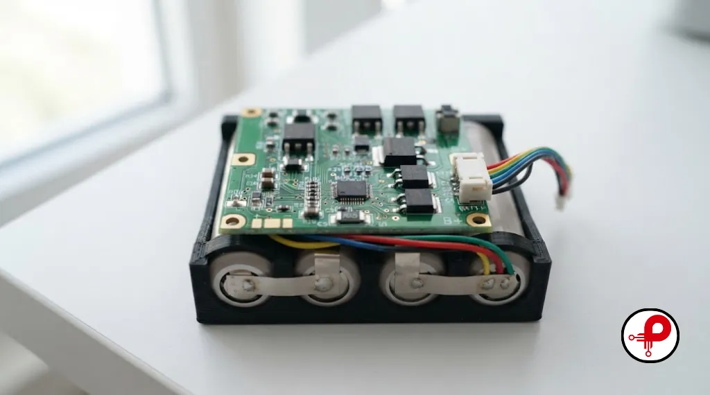
A battery management system is the electronic layer that sits between raw battery cells and the product they power. It measures voltage, current, and temperature, keeps individual cells balanced against each other, and steps in with protection circuitry the instant something drifts outside a safe window. Think of it as the nervous system of a battery pack. Without it, a lithium battery pack is just a bundle of cells waiting for one weak link to fail.
Battery management system design is not a single circuit you drop into a schematic and forget. It is a discipline that touches analog sensing accuracy, firmware control loops, thermal engineering, and PCB layout all at once. A pack with excellent cells but a poorly designed battery management circuit will still suffer premature capacity fade, thermal runaway risk, or nuisance shutdowns. That is why serious hardware teams treat BMS design with the same rigor as the mechanical enclosure or the power electronics that surround it.
The stakes get higher as pack size grows. A single cell BMS for a Bluetooth earbud has very different constraints than an EV battery management system built for a 400 volt pack. But the underlying principles of a battery management solution, accurate sensing, tight balancing, layered protection, and clean PCB layout, stay the same regardless of scale.
2. Core Functions Every Battery Management System Design Must Handle
Before diving into architecture and layout, it helps to define what a battery management system actually does day to day. Every solid battery management system design needs to cover these functions:
Individual Cell Monitoring
Voltage monitoring at the individual cell level, providing granular data rather than just pack terminal readings.
Current Path Management
Comprehensive current monitoring for both charge and discharge paths to ensure operational safety.
Multi-Point Thermal Sensing
Temperature monitoring at multiple points across the pack to prevent localized overheating.
State of Charge (SOC) Estimation
Precise SOC calculation so the user knows real remaining capacity at any given time.
State of Health (SOH) Tracking
Continuous SOH monitoring to make the pack’s aging and performance degradation visible over time.
Active & Passive Cell Balancing
Advanced balancing logic to keep every cell at a matched voltage for maximum efficiency.
Battery Protection Logic
Integrated protection circuit for overcharge, over-discharge, and short circuit event handling.
Host Communication Interface
Seamless communication with host controllers, chargers, or cloud platforms over UART, CAN, I2C, or SMBus.
Miss any one of these and the pack either underperforms or becomes a safety liability. This list is also a useful checklist when you are evaluating a vendor’s battery management solution or reviewing your own team’s schematic before tape out.
3. Battery Management System Architecture: Centralized, Modular, and Distributed
One of the first decisions in any battery pack design is picking the right battery pack architecture for the BMS itself. There are three common topologies, and each one trades off cost, complexity, and scalability differently.
| Architecture | Best For | Pros | Cons |
|---|---|---|---|
| Centralized | Small to mid packs, consumer electronics, e-bikes | Lower cost, simpler wiring, fewer PCBs | Long sense harnesses, harder to service, less scalable |
| Modular | EV packs, energy storage systems (ESS) | Easier to scale, shorter harness runs, isolated cell monitoring | Higher BOM cost, more firmware complexity for daisy chain sync |
| Distributed | Large-scale ESS, high-voltage EV packs | Best fault isolation, easiest to service individual modules | Highest cost, most complex communication network |
A centralized battery management system design places every sensing and protection circuit on one board. It is the simplest and cheapest option, and it works well for smaller multi cell battery packs. Once you scale into EV battery management system territory, though, a single board becomes impractical. That is where modular designs take over, using multiple cell monitoring units connected to a master controller, each handling a subset of cells. Distributed architectures push this even further by giving every module its own local intelligence, which is common in large energy storage battery management deployments where a single faulty module should never take the whole system offline.
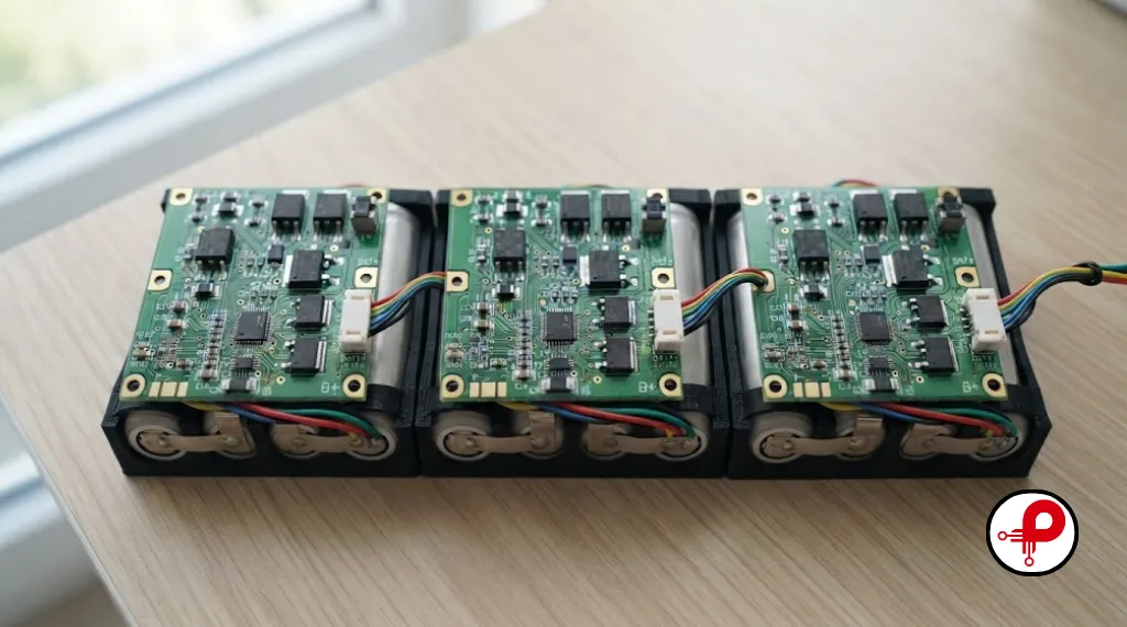
If your product roadmap includes scaling from a prototype to a production battery pack architecture with hundreds of cells, it pays to think about this decision early. Teams that start with a rigid centralized battery management system design often end up doing a full board respin when the product line grows, which is an expensive lesson to learn late. If you are still shaping the surrounding hardware, our guide on industrial product design engineering covers how architecture decisions ripple through mechanical and thermal design too.
4. Key Components in a Battery Management Circuit
A battery management circuit is built from a handful of functional blocks. Understanding what each one does makes it much easier to read a BMS schematic or evaluate a reference design.
Analog Front End (AFE)
The sensing layer that measures cell voltages with high precision and often integrates balancing drivers. These are typically daisy-chained across series cells.
Microcontroller (MCU)
The system’s brain; it runs SOC/SOH algorithms and protection logic. Automotive-grade designs often use ARM Cortex MCUs with real-time OS for deterministic fault response.
Current Sensing
Shunt resistors or Hall effect sensors track current in both paths, providing the essential data required for accurate coulomb counting.
Temperature Sensing
NTC thermistors strategically placed near cells, balancing resistors, and MOSFETs to monitor thermal health and prevent overheating.
Protection MOSFETs
A pair of charge/discharge MOSFETs acting as the final physical disconnect point when a critical fault condition is detected.
Balancing Circuit
Passive bleed resistors or active charge transfer components used to even out voltage differences across individual battery cells.
Communication Interface
UART, CAN, I2C, or SMBus links that enable the BMS to communicate with external chargers, host devices, or cloud platforms for remote monitoring.
Each of these blocks needs to be selected with the target chemistry, voltage, and current in mind, which is why a battery management solution for a LiFePO4 power tool pack looks very different from one built for a high current EV drivetrain.
5. Cell Balancing Techniques Compared

Cell balancing might be the single most misunderstood part of battery management system design. Without it, the weakest cell in a series string ends up defining the usable capacity of the entire pack, because the BMS has to stop charging or discharging as soon as that one cell hits its limit.
| Balancing Type | How It Works | Typical Current | Efficiency | Cost |
|---|---|---|---|---|
| Passive balancing | Bleeds excess energy from higher voltage cells through a resistor as heat | 20 to 100 mA | Lower, energy is wasted as heat | Low |
| Active balancing | Transfers charge from stronger cells to weaker ones using capacitors or inductors | Up to roughly 2 A | Higher, energy is reused | High |
Passive cell balancing is simple, cheap, and reliable, which is why it dominates consumer electronics and lower cost multi cell battery packs. Active cell balancing is more efficient and better suited to large packs where every percentage point of usable capacity matters, such as EV battery management system designs or grid scale storage. The tradeoff is added component count and design complexity on the battery management circuit. Neither approach is universally “better.” The right choice depends on pack size, budget, and how much you value marginal capacity gains against added BOM cost.
6. The Battery Management System Design Process, Step by Step
Here is the sequence I walk teams through when starting a new battery management system design from scratch.
Analyze voltage windows and thermal behavior for your specific chemistry. Finalize series and parallel configurations before schematic capture.
Select between centralized, modular, or distributed topologies based on total cell count, space constraints, and scalability requirements.
Match the Analog Front End (AFE) accuracy to your pack. Select an MCU with sufficient compute overhead for complex SOC/SOH algorithms.
Select components rated for worst-case current. Set precise firmware thresholds for overcharge, over-discharge, and short-circuit protection.
Determine the optimal balancing method (passive vs. active) and size bleed resistors or charge transfer components to maintain cell voltage equilibrium.
Design with strict attention to thermal paths and signal integrity, as layout-induced noise is a primary driver of field and validation failures.
Perform bench testing under thermal/current extremes and induce hardware faults to verify firmware responsiveness and safety shutdown logic.
Skipping steps, especially step 7, is the most common reason a battery management system design that looked perfect on paper fails in the field.
7. BMS PCB Design Best Practices
This is the section most BMS PCB design guides gloss over, and it is exactly where a lot of production issues come from. A battery management circuit has to handle high current power paths, sensitive analog sensing, and sometimes high voltage isolation, all on the same board.
Follow IPC-2152 for current-carrying capacity and IPC-2221 for critical creepage/clearance distances, especially for high-voltage battery strings.
Use 3–4 oz copper for high-current paths to minimize heat generation, while keeping logic/sensing traces to standard 1–2 oz weight.
In multilayer designs, dedicate an entire internal layer to ground to ensure low-impedance return paths and shield sensitive analog traces from noise.
Route current sense traces as true Kelvin pairs directly to the ADC to prevent ground loops that cause inaccurate SOC estimation.
Place TVS diodes on all exposed cell sense lines and external communication interfaces to protect sensitive ICs from transients.
Physically separate high-voltage nets and low-voltage logic on opposite sides of the board to reduce flashover risks and simplify safety compliance.
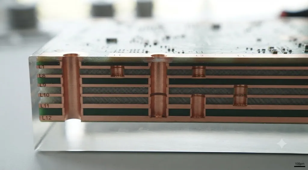
EMI and signal integrity deserve special attention because a battery pack’s switching MOSFETs and high current paths are aggressive noise sources. If your BMS PCB design will sit near a Bluetooth radio or other RF sensitive component, it is worth reading our deep dive on EMI issues, causes, examples, and fixes and our guide to minimizing EMI in a 4 layer PCB layout, both of which apply directly to BMS power stages. For teams building high current battery packs alongside switching converters, our article on high frequency switching noise issues walks through the coupling paths that most often trip up first time layouts. Once your board passes internal review, formal validation against electromagnetic compatibility testing requirements will save you from a failed compliance run late in the program.
Grounding, trace width, stack up planning, and routing decisions are not cosmetic choices. They determine whether your battery management circuit reports accurate voltage and current data or drifts by tens of millivolts under load, which directly affects SOC accuracy and, ultimately, how much usable battery life your customer actually gets.
8. Battery Protection System Essentials
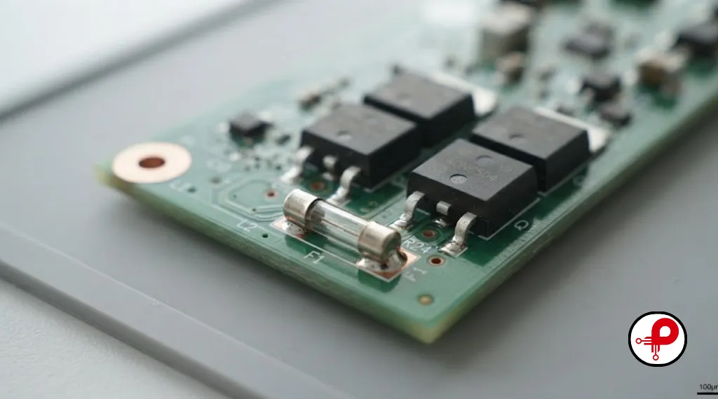
A battery protection system is the layered set of circuits and firmware thresholds that keep a pack from entering a dangerous state. Good battery management system design treats protection as redundant, not single point.
Overcharge protection stops charging current the moment any cell hits its upper voltage limit, well before the chemistry’s true damage threshold.
Over-discharge protection disconnects the load before any cell drops below its safe minimum voltage, since deep discharge accelerates capacity fade and, in some chemistries, creates internal shorting risk.
Short circuit protection relies on fast acting comparators or dedicated protection ICs that can respond in microseconds, faster than a microcontroller’s software loop ever could, because a hard short needs a hardware level response.
Thermal protection monitors cell and MOSFET temperature and progressively derates or shuts down current as limits are approached, rather than waiting for a single hard cutoff.
Fuses add a final, purely mechanical layer of redundancy behind all of the above. If every electronic layer fails simultaneously, which is rare but not impossible, a properly sized fuse is what stands between a fault and a fire. For packs built around lithium chemistry specifically, our detailed guide to lithium ion battery protection circuits breaks down threshold selection in more depth.
9. SOC, SOH, and Smart Battery Management
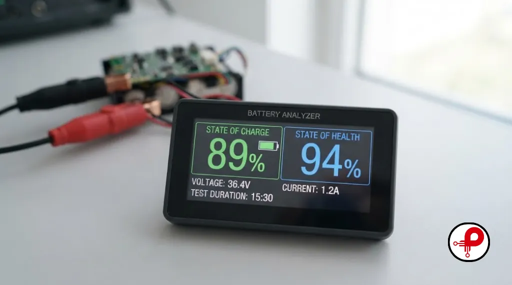
State of Charge tells the user how much usable energy remains right now. State of Health tells them how much capacity the pack has lost over its lifetime compared to when it was new. Both numbers depend entirely on the quality of the underlying battery monitoring system, since a coulomb counting algorithm is only as good as the current sensing feeding it.
A smart battery management system goes further than basic SOC and SOH tracking. It logs cycle history, adapts balancing behavior as the pack ages, and can flag a weak cell long before it causes a field failure. This is increasingly expected in intelligent battery management platforms for EVs and stationary storage, where fleet operators want predictive maintenance data, not just a percentage on a dashboard.
Getting SOC and SOH accuracy right is one of the clearest ways battery management system design translates directly into longer, more predictable battery life for the end user. A pack that reports SOC accurately lets a device use its full rated capacity instead of shutting down early out of an overly conservative safety margin.
10. LiFePO4 vs Li-ion Battery Management System Design
Not every lithium chemistry needs the same BMS design. A LiFePO4 battery management system and a standard Li-ion battery management system share the same core building blocks but differ in the details.
| Factor | LiFePO4 BMS Design | Li-ion BMS Design |
|---|---|---|
| Nominal cell voltage | Around 3.2V | Around 3.6 to 3.7V |
| Thermal stability | Higher, more forgiving thresholds possible | Lower, tighter thermal protection needed |
| Voltage curve | Flat, harder to estimate SOC from voltage alone | Steeper, easier voltage-based SOC estimation |
| Balancing needs | Still required, flat curve makes drift less visible | Critical, since voltage differences show up faster |
| Typical applications | Solar systems, e-bikes, backup power | EVs, consumer electronics, drones |
Because LiFePO4’s voltage curve is so flat across most of its state of charge range, a battery management system design for LiFePO4 needs a more sophisticated SOC algorithm, often blending coulomb counting with periodic voltage based correction, since voltage alone is a poor indicator of remaining charge for most of the discharge curve. This is a detail many first time designers miss when adapting a Li-ion reference design directly to a LiFePO4 pack.
11. Common Design Mistakes That Shorten Battery Life
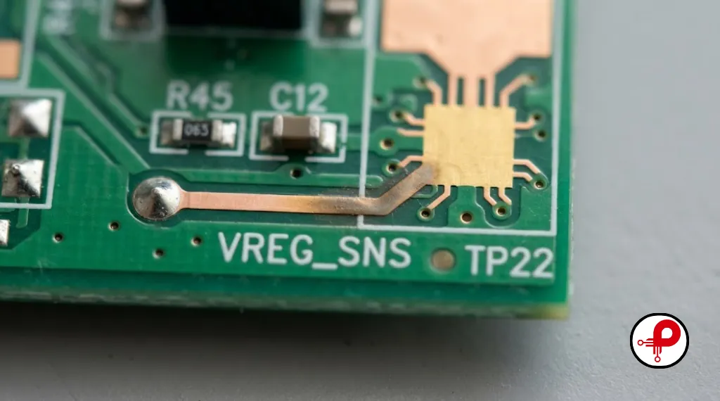
After reviewing enough battery management circuit designs, the same mistakes show up again and again.
- Undersized current sensing range, which clips readings during peak load and corrupts SOC calculations
- Single point temperature sensing, missing hot spots that develop away from the one thermistor
- Ignoring cell balancing until late in development, forcing a board respin to add balancing resistors
- Ground plane gaps under analog sensing traces, introducing voltage measurement errors of tens of millivolts
- Protection thresholds set at the chemistry’s absolute limit instead of with safety margin
- Skipping fault injection testing, so firmware only gets validated against normal operating conditions
Many of these mistakes are layout related and trace straight back to rushed PCB work. Our broader roundup of PCB design mistakes covers several of these patterns in more general terms, and it is worth a read even for teams confident in their schematic.
12. Choosing a Custom BMS Design Partner
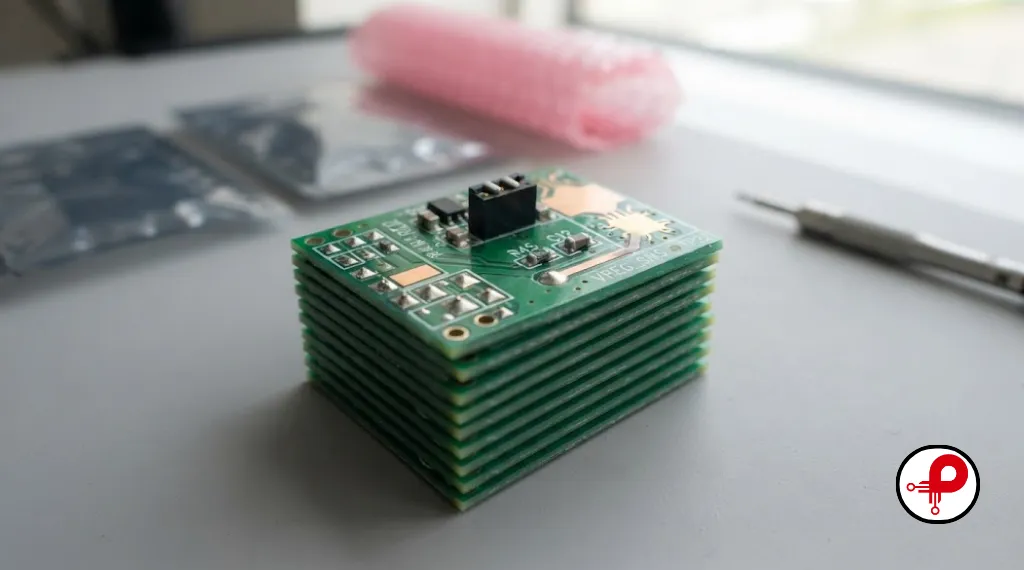
Off the shelf battery management solutions work fine for standard consumer products, but many applications, custom form factors, unusual chemistries, extreme temperature ranges, or specific certification targets, need a custom BMS design built around the actual product rather than a generic reference board.
When evaluating a partner for custom battery management system design, look for a track record across the full workflow: schematic capture, DFM aware PCB layout, EMI conscious stack up planning, and hands on validation testing, not just a datasheet reference design copied into a new footprint. If you are scoping a broader hardware program and the BMS is just one subsystem, our overview of the complete electronic product design workflow and our guide for hardware development for startups are good starting points before you lock in a BMS architecture. Consumer facing products carry their own set of constraints too, which our consumer electronics product design guide covers in detail, and if the pack needs to talk to a companion app, it is worth reading how BMS data typically reaches Bluetooth connected devices in an embedded system. Once the board is designed, understanding the PCB manufacturing process end to end helps avoid surprises between prototype and production runs.
13. A Real World Example: When BMS Design Determined Battery Life
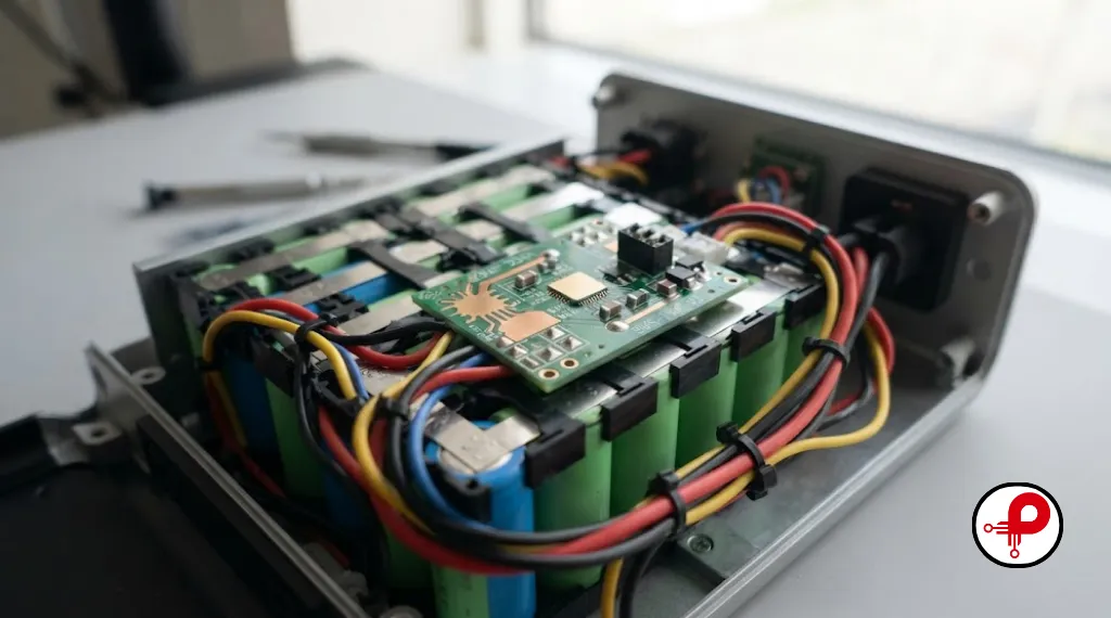
A few years back I worked with a startup building a portable power station using a 13 series lithium ion pack. Their first prototype used a centralized battery management system design with a single shared thermistor mounted near the MCU rather than distributed across the cell stack. In bench testing everything looked fine, but in the field, packs deployed in warmer climates started showing capacity fade nearly twice as fast as the lab units.
The root cause traced back to the battery protection system relying on one temperature reading that never saw the actual hot spot forming near the outer cells during fast charging. The firmware never throttled charge current because, as far as it knew, the pack was well within thermal limits. The fix was not a new chemistry or a different cell supplier. It was redesigning the battery monitoring system to place three thermistors across the pack and rewriting the thermal protection logic to derate based on the worst reading rather than a single averaged value. Cycle life in the field matched the lab numbers within a few percentage points after that change.
This kind of story is common in battery management system design. The cells are rarely the weak link. The sensing, the balancing strategy, and the PCB layout around those cells almost always are. It is also why any credible battery management solution vendor should be able to walk you through failure cases like this one rather than only showing you a clean reference design that has never been stress tested in the field.
14. How to Evaluate a Battery Management System Design on Paper
Before a board goes to fabrication, there are a handful of checks that catch the majority of downstream problems. These come from years of design reviews, and they apply whether you are looking at a simple single cell BMS or a full EV battery management system.
Avoid generic templates. Set protection voltage and temperature limits strictly based on the specific cell manufacturer’s datasheet to prevent safety risks.
Ensure current sensing covers motor start-up and inrush currents, not just nominal values, to prevent saturation during critical peak events.
Verify passive balancing current is sufficient for your charge rate; otherwise, voltage drift will accumulate over successive cycles.
Test your design under high-load, extreme-temperature conditions, rather than relying solely on room-temperature, low-load validation.
Validate communication protocols (CAN, SMBus, UART) early in the design phase to avoid late-stage integration failures.
Running through this list before committing to a PCB spin, rather than after the first prototype run, is consistently the cheapest point in the process to fix a battery management system design problem.
15. FAQ
1. What is the main purpose of a battery management system?
↑2. How do I design a battery management system for a small project?
↓3. What is the difference between active and passive cell balancing?
↓4. Why does BMS PCB design matter for battery life?
↓5. Is a LiFePO4 battery management system different from a Li-ion BMS?
↓6. What features should a modern battery management system include?
↓7. How do you test a battery management system after design?
↓8. Which microcontroller is best for battery management system design?
↓16. Final Thoughts
Battery management system design is where electrical engineering, firmware, and PCB layout all have to agree with each other. Get the architecture right, size the protection circuit with real margin, choose a balancing strategy that fits the pack, and respect IPC standards and EMI best practices on the PCB, and the result is a battery pack that actually delivers the cycle life its cells were rated for. Cut corners in any one of those areas, and no amount of cell quality will save the product from underperforming or, worse, failing in the field.
If you are early in a hardware program and want a second set of eyes on your battery management system design before committing to a PCB spin, it is far cheaper to catch these issues at the schematic stage than after the first production batch ships.