








Quick answer: The CH224K is a low-cost USB Power Delivery sink controller from WCH that negotiates 5V, 9V, 12V, 15V, or 20V from a USB-C PD charger without needing a microcontroller. It also supports Quick Charge, BC1.2, and other legacy fast-charging protocols, making it one of the most common chips inside USB-C PD trigger boards, decoy modules, and DIY bench power supplies.
If you have ever pulled apart a USB-C “PD trigger board” from a marketplace listing, chances are you found a tiny eight-pin or ten-pin chip doing all the heavy lifting. In the vast majority of cases, that chip is the CH224K. After spending years designing power stages for embedded products, I keep coming back to this part because it solves a problem that used to require a full protocol stack and a dedicated PD controller costing several times as much.
This guide walks through what the CH224K actually does, how its pinout and configuration pins work, how to wire a working circuit around it, and where it fits against alternatives like the STUSB4500 or IP2721. Whether you are specifying it for a product or just trying to get 20V out of a phone charger for a soldering iron, you will find the practical detail here that most datasheets skip.
What Is the CH224K USB PD Trigger Module?
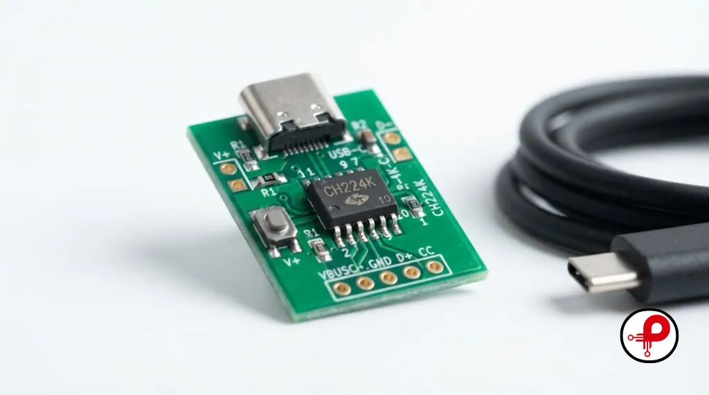
Definition: The CH224K is a USB Power Delivery and multi-protocol fast-charging sink controller manufactured by Nanjing Qinheng Microelectronics (WCH). It sits between a USB-C connector and the rest of a circuit, automatically handling the handshake needed to request a specific voltage from a compliant charger.
Unlike a plain USB-C connector, which only guarantees 5V at low current unless something actively negotiates for more, a PD source will not hand over 9V, 12V, 15V, or 20V unless a device on the other end asks for it correctly. That negotiation involves USB Power Delivery messaging over the CC (configuration channel) line, and getting it wrong with a general-purpose microcontroller means writing and maintaining a PD protocol stack. The CH224K removes that burden by handling the entire negotiation internally, in silicon, and simply exposing three configuration pins that let you pick the requested voltage.
This is why the chip shows up constantly in USB-C PD trigger boards, USB-C power delivery decoy boards, bench power supply front ends, laptop dock power stages, soldering iron power modules (like many GX16 and USB-C powered irons), and embedded products that need to draw more than the standard 5V/500mA from a USB-C source, including maker boards like the ESP32. If you are pairing a CH224K supply with an ESP32 project, our ESP32 board URL setup guide for Arduino IDE covers the toolchain side of that build.
In DIY electronics and hobbyist electronic projects, and in more disciplined embedded electronics builds alike, the CH224K’s power negotiation logic makes it a natural fit for any compact PD sink module or PCB module that needs to slot into an existing Type-C power supply circuit without dragging in a full development board. It also works well as the electronic circuit behind a bench-built voltage selector, letting you tap 5V through 20V from whatever USB-C power adapter happens to be on the desk.
Choosing a chip like this rarely happens in isolation. It is usually one decision inside a much larger electronic product design workflow, where power architecture, connector selection, and firmware all have to line up before a board goes to fabrication.
Depending on where you encounter it, the same hardware gets called a few different things: a CH224K PD trigger, a USB Type-C PD trigger module, a USB PD voltage trigger module, or simply a USB-C Power Delivery Trigger Board. All of these names point to the same underlying chip and the same job, requesting a fixed or selectable voltage from a USB-C charger. This guide uses CH224K USB PD trigger module as the umbrella term throughout, since that is how most engineers search for it, but do not be thrown off if a listing or datasheet calls it something slightly different.
Quick Facts Box
| Attribute | Detail |
|---|---|
| Manufacturer | WCH (Nanjing Qinheng Microelectronics) |
| Protocols supported | USB PD 3.0/2.0, BC1.2, and other common fast-charge protocols |
| Max power | Up to 100W (20V at 5A) |
| Output voltages | 5V, 9V, 12V, 15V, 20V |
| Configuration methods | Single resistor, I/O level (CFG1/CFG2/CFG3), I2C on select variants |
| Typical package | ESSOP-10 / SOP |
| Logic voltage tolerance | CFG2/CFG3 pins rated up to roughly 3.7V; treat as 3.3V logic only |
CH224 Chip Family Comparison
The CH224K is one member of a broader family, and confusing the variants is one of the most common mistakes engineers make when sourcing this part. Here is how they differ.
| Chip | Release | Max Power | Configuration | I2C | Notes |
|---|---|---|---|---|---|
| CH221K | 2018 (earliest) | 100W | Single resistor only | No | No D+/D- lines, PD only, very compact |
| CH224K | 2019 | 100W | Resistor or I/O level | No | Most widely used variant, 3.3V logic on CFG pins |
| CH224D | 2019 | 100W | Resistor or I/O level | No | Functionally identical to CH224K, different package, 5V tolerant CFG pins |
| CH224A | 2024 | Up to 140W (PD3.2 EPR) | Resistor, I/O level, or I2C | Yes | Pin-compatible drop-in replacement for CH224K |
| CH224Q | Newer | Up to 140W (PD3.2 EPR) | Resistor, I/O level, or I2C | Yes | Same generation as CH224A, extended feature set |
If you are starting a new design today, it is worth checking current stock and datasheets for CH224A or CH224Q, since WCH has been positioning them as the long-term replacement for CH224K while keeping the pinout largely compatible. That said, CH224K remains cheap, well documented by the hobbyist community, and extremely common in ready-made trigger boards, so it is not going away from the secondary market anytime soon.
CH224K USB PD Trigger Module Features and Specifications
Marketed under names such as the CH224K USB-C module, CH224K fast charging module, and CH224K USB-C fast charging module, these products all share the same core functionality. Regardless of branding, each module uses the CH224K chip to negotiate USB Power Delivery voltages from compatible USB-C chargers. This allows users to obtain fixed output voltages like 5V, 9V, 12V, 15V, or 20V for powering electronic projects, embedded systems, prototypes, and portable devices without requiring a microcontroller.
1. USB PD 3.0 & 2.0 Negotiation
Supports USB PD 3.0 and PD 2.0 negotiation without an external MCU or protocol stack.
2. Fast-Charge Backward Compatibility
Backward compatible with BC1.2 and other common fast-charge signaling used by USB-A chargers.
3. Automatic E-Marker Detection
Automatic detection of VCONN and analog E-Marker chips inside PD cables.
4. Built-in High-Voltage LDO
Built-in high-voltage LDO for internal biasing, reducing external component count.
5. Integrated Output Protection
Integrated output voltage detection with over-voltage and over-temperature protection.
6. Power Good (PG) Output
Open-drain Power Good (PG) output that can drive an LED or a P-channel MOSFET for load switching.
7. Flexible Configuration Modes
Three configuration modes: single resistor, three-pin I/O level select, and (on newer siblings) I2C.
8. Compact Package Design
Small ESSOP-10 style package suited to compact trigger boards and embedded designs.
9. Low Quiescent Current
Low quiescent current, useful in always-on or battery-adjacent designs.
These features matter in practice. The PG pin, for example, is what most trigger board designs use to switch on downstream circuitry only after the requested voltage has actually been negotiated and is present, rather than assuming negotiation succeeded.
CH224K USB PD Trigger Module Pinout Explained
The CH224K is typically offered in a 10-pin ESSOP/SOP package. Pin numbering and exact labels can vary slightly between datasheet revisions, so always confirm against the specific package variant you are using, but the functional pin map is consistent across boards built around this chip.
| Pin Function | Description |
|---|---|
| VBUS | USB-C VBUS input, connects to the negotiated power rail from the source |
| GND | Ground reference |
| CC1 / CC2 | Configuration channel lines, connect directly to the USB-C connector’s CC pins |
| DP / DM | USB 2.0 data lines, used for BC1.2 and legacy fast-charge protocol detection |
| CFG1 | Primary configuration pin; sets single-resistor mode or enables I/O level mode |
| CFG2 | Secondary configuration pin, used in I/O level mode |
| CFG3 | Tertiary configuration pin, used in I/O level mode |
| PG (Power Good) | Open-drain output, pulls low when the requested voltage has been successfully negotiated |
| VDD | Internal logic supply, typically around 3.3V, generated by the chip’s internal LDO |
Electrical Characteristics
| Parameter | Typical Value | Notes |
|---|---|---|
| VDD (internal logic supply) | 3.3V typical, 3.6V max | Generated internally, do not force externally without a series resistor |
| CFG2 / CFG3 max input voltage | Around 3.7V | Treat as strict 3.3V logic, not 5V tolerant on CH224K |
| CFG1 max input voltage | Higher tolerance than CFG2/CFG3 on CH224K | Still confirm exact rating in the current datasheet revision before driving from 5V logic |
| Output voltage range | 5V to 20V (4V to 22V request range per datasheet) | Actual delivered voltage depends on source PDO support |
| Max continuous power | Up to 100W | Requires a cable and source that both support the requested wattage |
| I2C clock rate (CH224A/Q only) | Up to 400kHz | Not available on standard CH224K |
A note from experience: the CFG2 and CFG3 pins on the CH224K are not 5V tolerant, while CH224D’s equivalent pins are rated for 5V. This single difference has caused more than one blown chip when engineers swap parts between the two variants without re-checking the logic-level requirements. If your controlling MCU runs at 5V logic, either use CH224D instead or add a level shifter or series resistor network ahead of CFG2/CFG3 on a CH224K. Before committing a design, always cross-check these figures against the current CH224K USB PD trigger module datasheet published by WCH, since electrical limits have shifted slightly between revisions.
How Voltage Negotiation Works
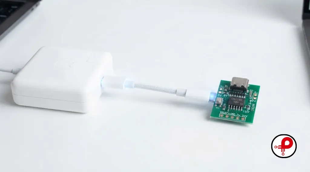
USB Power Delivery is a message-based protocol carried over the CC line of a USB-C connector, not a simple analog voltage select. The behavior described here follows the official USB Power Delivery specification maintained by the USB Implementers Forum, which defines exactly how a source and sink exchange these messages. When a PD source is plugged in, it advertises a list of Power Data Objects (PDOs), each describing a voltage and current combination it can supply, such as 5V/3A, 9V/3A, 15V/3A, and 20V/5A.
The CH224K listens to these advertisements, compares them against the voltage you have configured through its CFG pins (or, on the newer variants, through I2C), and sends a Request message back to the source asking for the matching PDO. If the source supports that PDO, it switches VBUS to the requested voltage and the CH224K’s PG pin goes low to confirm success. If the requested voltage is not available, the CH224K falls back according to its internal logic, and PG remains high, indicating no successful negotiation.
This is also why a CH224K trigger board will never output more than what the connected charger actually supports. A charger that only advertises 5V, 9V, and 12V PDOs will simply not deliver 20V, no matter how the CFG pins are set. Always check the charger’s own PD profile if a trigger board is not reaching the expected voltage; the module is frequently not the fault.
How to Use CH224K USB PD Trigger Module: Configuration Methods
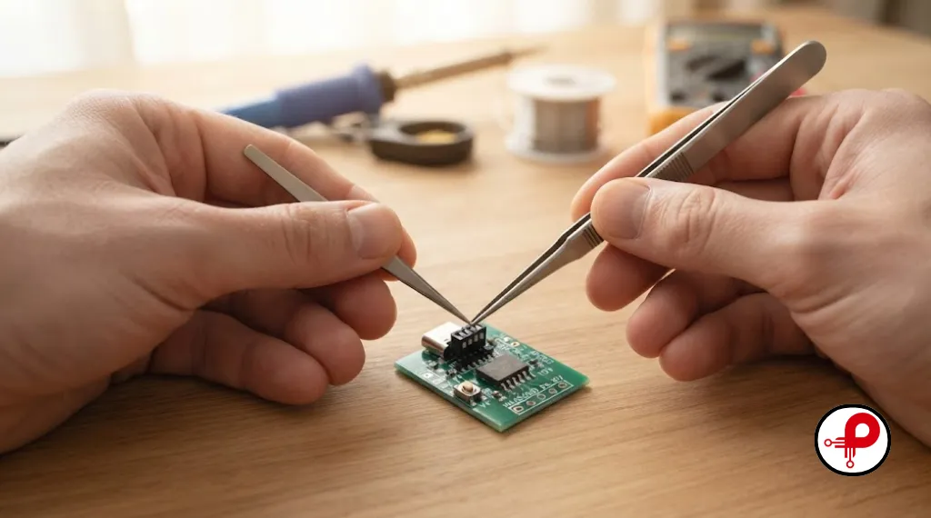
Method 1: Single Resistor Configuration
This is the simplest and cheapest approach, and it is what most fixed-voltage trigger boards use. A single resistor is placed between CFG1 and ground, and CFG2/CFG3 are left unused. Different resistor values correspond to different fixed output voltages. This method is ideal when the target voltage never needs to change after the board is built, such as inside a product that always needs 12V from its USB-C input.
Method 2: I/O Level Configuration (Three-Pin Select)
This is the most common method in adjustable trigger boards, including the popular switch-based and button-based modules sold for bench use. CFG1, CFG2, and CFG3 are each driven high or low, either by DIP switches, jumpers, or GPIO pins from a microcontroller, and the combination of states selects the output voltage. This is the method used in DIY projects such as ATtiny-based PD trigger and monitoring boards, where the microcontroller can change voltage dynamically based on button presses or serial commands.
Method 3: I2C Configuration (CH224A / CH224Q Only)
Standard CH224K does not support I2C. If your design needs a microcontroller to read back the negotiated protocol status, rated current, or dynamically request voltages beyond a simple three-pin combination, the CH224A or CH224Q variants add a 400kHz I2C interface for exactly this purpose. If you are designing a new smart power module rather than replicating an existing CH224K board, this is worth strong consideration.
CH224K USB PD Trigger Module Voltage Settings (CFG Pin Table)
This is the table most people search for when trying to reverse-engineer or design a switch-based trigger board, covering the full USB PD trigger module 5V 9V 12V 15V 20V range in one lookup. It doubles as a quick reference for CH224K voltage selection whether you’re wiring switches or driving the pins from firmware.
| Output Voltage | CFG1 | CFG2 | CFG3 |
|---|---|---|---|
| 5V | High (1) | Don’t care | Don’t care |
| 9V | Low (0) | Low (0) | Low (0) |
| 12V | Low (0) | Low (0) | High (1) |
| 15V | Low (0) | High (1) | High (1) |
| 20V | Low (0) | High (1) | Low (0) |
A few practical notes worth remembering:
- Leaving CFG1 floating during power-up can cause the chip to default toward a high-voltage request before your MCU has finished booting. If your downstream circuit cannot tolerate 20V, add a pull resistor on CFG1 so a safe default voltage is requested before firmware takes control.
- CFG2 and CFG3 should not be left floating either. Add defined pull-up or pull-down resistors so their state is deterministic from power-on, not random.
- DIP switch based trigger boards typically wire “switch ON” to a logic low and “switch OFF” to a logic high internally, which is the reverse of what many people assume. Always verify with a multimeter on the specific board you have, since silkscreen conventions vary between manufacturers.
CH224K USB PD Trigger Module Wiring Diagram and Circuit
A minimal fixed-voltage CH224K circuit needs surprisingly few external components, and this same layout forms the basis of most CH224K wiring diagram references you’ll find online:
USB-C receptacle with CC1 and CC2 connected directly to the chip’s CC1 and CC2 pins.
A single configuration resistor from CFG1 to ground, sized according to the target voltage per the datasheet’s resistor table.
Bulk input capacitance on VBUS, typically in the 10 to 47 microfarad range, to handle inrush and negotiation transients.
An optional Power Good LED, wired through a current-limiting resistor from a pulled-up PG pin to ground, so it lights when negotiation succeeds.
If gating downstream power, a P-channel MOSFET on the high side with its gate driven by the PG pin, so load current only flows once the correct voltage is confirmed present.
For an adjustable board using I/O level mode, replace the single resistor with three switches or GPIO connections to CFG1, CFG2, and CFG3, following the truth table above, and add defined pull resistors as discussed earlier.
Best practice: Keep the CC1/CC2 traces short and away from noisy high-current traces. USB PD negotiation is sensitive to signal integrity on the CC lines, and a poorly routed board can intermittently fail to negotiate higher voltages even though the CH224K itself is functioning correctly. If you are new to the distinction between schematic capture and physical routing, our explainer on PCB design vs PCB layout is a good place to start before you commit to a board revision.
At higher power draw, especially 15V and 20V requests near the 100W ceiling, trace width and copper pour around VBUS matter more than most first-time designers expect. It is worth reviewing general circuit board design rules alongside the CH224K’s own reference layout before finalizing a board that will run at full load for extended periods.
CH224K vs Other USB PD Trigger Chips
| Chip | Max Power | Config Method | I2C | Approx. Cost | Best For |
|---|---|---|---|---|---|
| CH224K (WCH) | 100W | Resistor / I/O level | No | Very low | Simple fixed or switch-selected trigger boards |
| CH224A / CH224Q (WCH) | Up to 140W (EPR) | Resistor / I/O level / I2C | Yes | Low | New designs needing higher power or MCU feedback |
| STUSB4500 (STMicroelectronics) | Depends on source, up to 100W | I2C with NVM-stored profiles, autonomous mode | Yes | Moderate | Products needing configurable PDO profiles without runtime firmware |
| FUSB302 (onsemi) | Depends on source | Full I2C, requires external PD stack/firmware | Yes | Moderate | Designs needing full custom PD stack control |
| IP2721 (Injoinic) | Up to 100W | Resistor / pin select | No | Very low | Similar niche to CH224K, common in Chinese-market trigger boards |
The CH224K’s main advantage over parts like the STUSB4500 or FUSB302 is that it requires zero firmware and zero I2C setup for the most common use case: request a fixed voltage and confirm it landed. The STMicroelectronics STUSB4500 is a stronger choice when a product needs to store custom PDO profiles in non-volatile memory and behave autonomously without any host microcontroller present at all, since it can operate standalone once configured. The FUSB302 sits at the other end of the spectrum, offering full protocol flexibility at the cost of needing a real PD stack running on a host MCU, which is more development effort than most trigger-board use cases justify.
CH224K USB PD Trigger Module Applications
1. USB-C PD Trigger and Decoy Boards
USB-C PD trigger and decoy boards for bench testing power adapters.
2. DIY Variable Power Supplies
DIY variable power supplies built around a PD charger and a downstream buck or buck-boost converter.
3. USB-C Powered Soldering Irons
USB-C powered soldering irons and hot air stations that need 20V for fast heat-up.
4. Docking Stations
Laptop and monitor docking stations that need to pass through negotiated PD power.
5. Portable Instrument & Test Equipment
Portable instrument and test equipment that draws power from any USB-C PD charger instead of a proprietary barrel-jack adapter.
6. Embedded Products & Robotics
Embedded products (single-board computers, camera rigs, robotics platforms) that need more than the standard 5V/500mA USB budget.
7. Battery Charging Front Ends
Battery charging front ends that use PD negotiation to select an efficient charge voltage before a dedicated charge-management IC takes over.
8. Compact Wireless Gadgets
Compact wireless-enabled gadgets, where the power stage sits close to RF sections; keep the two circuits from interfering with each other.
9. Wearable & Body-Worn Electronics
Wearable and body-worn electronics that dock to charge at higher wattage, balancing power and form-factor tradeoffs.
10. Regulated Bench & Clinical Equipment
Regulated bench and clinical equipment prototypes, where power architecture decisions intersect with broader medical device compliance requirements.
- USB-C PD trigger and decoy boards for bench testing power adapters
- DIY variable power supplies built around a PD charger and a downstream buck or buck-boost converter
- USB-C powered soldering irons and hot air stations that need 20V for fast heat-up
- Laptop and monitor docking stations that need to pass through negotiated PD power
- Portable instrument and test equipment that draws power from any USB-C PD charger instead of a proprietary barrel-jack adapter
- Embedded products (single-board computers, camera rigs, robotics platforms) that need more than the standard 5V/500mA USB budget
- Battery charging front ends that use PD negotiation to select an efficient charge voltage before a dedicated charge-management IC takes over
- Compact wireless-enabled gadgets, where the power stage sits close to RF sections; if your project also includes an onboard antenna, see our notes on 2.4 GHz PCB antenna design to keep the two circuits from interfering with each other
- Wearable and body-worn electronics that dock to charge at higher wattage; our piece on the development of wearable technology covers some of the power and form-factor tradeoffs involved
- Regulated bench and clinical equipment prototypes, where power architecture decisions intersect with the broader medical device development process and its compliance requirements
It’s also a popular choice as an Arduino power supply front end, an ESP32 power supply for bench testing without a separate adapter drawer, or a Raspberry Pi power supply when the standard 5V rail is not enough for attached peripherals. In each case, the chip’s DC output feeds directly into the board’s USB-C or barrel input once negotiation succeeds. The same design shows up as a QC trigger module recovered from an old decoy board and repurposed into a fresh portable power supply project, or wired inline with a USB-C power adapter to build a simple bench voltage selector for testing purposes. Some engineers also use it as a compact DC power module bolted onto an existing supply rather than designing a new one from scratch.
Common Mistakes and Troubleshooting
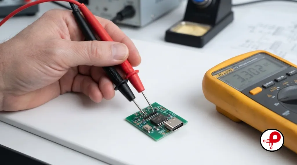
Board only outputs 5V, never negotiates higher. Check the charger itself first; not every USB-C charger supports PD, and many phone chargers only support Quick Charge over USB-A, which the CH224K can also detect, but the CC-based PD path requires a genuine PD source and a compliant cable. Also verify CFG pin states with a multimeter rather than trusting the silkscreen.
PG pin never goes low. This usually means the requested voltage was not granted. Confirm the source actually advertises that PDO (many 45W and lower chargers do not offer 20V), and confirm the CFG combination matches the table above exactly, since a single misconfigured pin will request the wrong PDO.
Chip runs hot or resets under load. This is often a cable problem, not a chip problem. Cables without a proper E-Marker chip are not certified for higher wattages, and some non-compliant cables will cause the source to refuse or truncate high-power PDOs. Use a cable rated for the wattage you are requesting. If heat is showing up on the board itself rather than the cable, revisit copper pour and component placement using general thermal management in PCB design principles before assuming the chip is faulty.
CFG pins damaged after connecting to 5V logic. This is the classic CH224K vs CH224D confusion mentioned earlier. CFG2/CFG3 on CH224K are not 5V tolerant. If this has already happened, replace the chip; there is no reliable recovery once the input protection has been overstressed.
Board powers on but load switching is erratic. If you are using PG to drive a P-channel MOSFET, verify PG has an adequate pull-up resistor value for your MOSFET’s gate threshold, and confirm PG is genuinely open-drain on your board revision, since some clone boards route it differently than the reference schematic. Before assuming a design flaw, run the board through a proper bring-up sequence; our guide to PCB testing and inspection walks through the checks worth doing before blaming the chip.
Advantages vs Disadvantages
| Advantages | Disadvantages |
|---|---|
| No firmware or protocol stack required | Standard CH224K lacks I2C feedback |
| Very low cost, widely available | CFG2/CFG3 not 5V tolerant on CH224K |
| Small footprint, low external component count | Being gradually phased toward CH224A/Q by WCH |
| Handles PD plus several legacy fast-charge protocols in one chip | Cannot generate power itself; fully dependent on source capability |
| Simple resistor or switch-based voltage selection | Documentation historically translated from Chinese, occasional ambiguity |
Design Best Practices
- Always add defined pull resistors on CFG1, CFG2, and CFG3 rather than leaving any of them floating at power-up.
- Match logic voltage to the correct chip variant: use CH224D or add level shifting if your control logic runs above 3.3V.
- Use a PD-certified cable with an E-Marker for any request above 60W, and remember the 100W ceiling assumes both cable and source support it.
- Route CC1/CC2 as short, clean traces away from switching regulators or other noise sources.
- Add bulk capacitance on VBUS to smooth negotiation transients and reduce brownout risk during voltage switching.
- Gate downstream loads through the PG signal rather than assuming negotiation success, especially in products shipped to end users who may plug in non-PD chargers.
- If your project may need I2C feedback or higher EPR power levels later, evaluate CH224A or CH224Q up front rather than redesigning later, since the migration path is straightforward but easier to plan early.
- Pick every supporting passive deliberately rather than reusing a value from an unrelated project; our electronic component selection guidelines cover how to choose tolerances, voltage ratings, and package sizes that actually match a PD-powered design.
Buying Guide: Ready-Made Modules vs Bare Chip
Whether you’re buying a ready-made USB PD voltage trigger module or sourcing the bare chip yourself, the decision usually comes down to volume and how much you want to customize the footprint. The broader USB Power Delivery trigger market has enough options that price and documentation quality vary a lot between listings, so it pays to compare a few before committing.
If you only need to power a single project at a fixed voltage, a ready-made switch-select board is the fastest path. If you are designing a product for manufacturing, sourcing the bare chip, such as through a distributor listing like CH224K on LCSC, and building the reference circuit into your own PCB will be cheaper at volume and lets you control the footprint precisely.
Moving from a hobbyist prototype to a shipping product is where most of the real risk sits, and it rarely has anything to do with the chip itself. If you are weighing that jump, it is worth reading up on why hardware startups fail before committing to a production run, since sourcing, testing, and cash flow issues sink far more hardware projects than component selection does.
Frequently Asked Questions
1. What is the CH224K USB PD trigger module used for?
↑2. Is the CH224K the same as the CH224D?
↓3. Can the CH224K generate 20V by itself?
↓4. What is the maximum power the CH224K supports?
↓5. Why is my CH224K board stuck at 5V?
↓6. Can I control the CH224K voltage with a microcontroller?
↓7. What is the difference between CH224K and CH224A?
↓8. How do I know if my requested voltage was successfully negotiated?
↓Conclusion
The CH224K USB PD trigger module earns its popularity honestly. It turns a genuinely complex protocol negotiation into three logic pins and a handful of passive components, which is why it shows up in everything from two-dollar trigger boards to purpose-built bench power supplies. Understanding its pinout, its CFG truth table, and its logic-level limitations is usually enough to avoid the handful of mistakes that trip up most first-time users, from floating configuration pins to mismatched logic voltages.
If you are speccing a new product today, weigh whether the added I2C feedback and higher EPR ceiling of the CH224A or CH224Q variant are worth the small design change over the standard CH224K USB PD trigger module. For most hobbyist and low-volume projects, the CH224K remains the fastest, cheapest way to pull real power out of any USB-C PD charger sitting in a drawer.
Have a CH224K USB PD trigger module circuit that is not negotiating the way you expect? Double-check the CFG pin states against the table above and confirm your charger actually advertises the PDO you are requesting; those two checks resolve the overwhelming majority of reported issues.