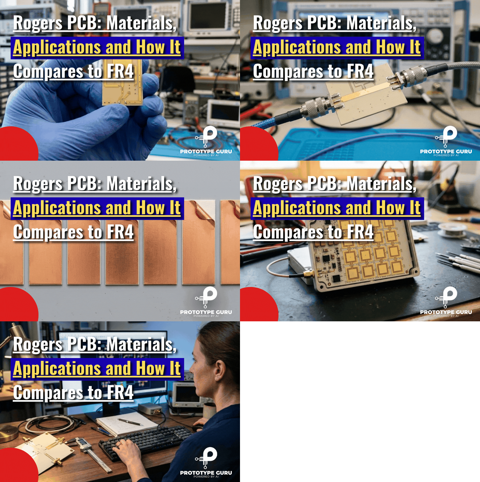









A Rogers PCB is a printed circuit board built on high frequency laminate made by Rogers Corporation, instead of on standard FR4. Rogers makes the material, and a PCB fabricator turns that material into your board. Engineers choose it for one main reason: its dielectric constant stays low and stable, and its signal loss is far lower than FR4 at GHz frequencies.
That difference matters once your design moves into RF, microwave or very fast digital territory. At 10 GHz, a popular Rogers laminate such as RO4350B loses only a fraction of the signal energy that a typical FR4 loses.
This guide covers what a Rogers PCB really is, the key material properties, the seven best known Rogers laminates with verified datasheet values, a direct comparison with FR4, the main applications, hybrid stackups, and a practical checklist for designing and ordering your first board.
What Is a Rogers PCB?
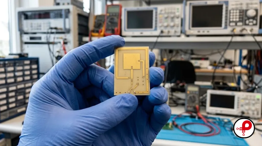
A Rogers PCB is any circuit board whose dielectric layers use laminates from Rogers Corporation, an American materials company. The name describes the material, not the factory. Many online guides get this wrong and say Rogers “manufactures” the boards. In reality, Rogers sells laminate and prepreg, and fabricators such as your local or Asian PCB house build the finished board.
The reason these boards exist is simple. Standard FR4 works very well for most electronics, but its dielectric constant drifts with frequency and its loss climbs as signals get faster. A Rogers PCB keeps those values tightly controlled, so RF engineers can predict impedance, phase and loss with confidence.
Who Makes Rogers PCB Materials?
Rogers Corporation, through its Advanced Electronics Solutions business, makes the laminates. It sells them under product families such as RO4000, RO3000, RT/duroid and TMM.
Other companies make competing high frequency materials too, including Taconic (now part of AGC), Isola, Panasonic and Arlon. Engineers often still say “Rogers PCB” as a general name for any low loss RF board, much as people say “FR4” for any glass epoxy laminate.
What Is Rogers PCB Material Made Of?
Rogers PCB material comes in three main types:
- Hydrocarbon ceramic with woven glass: the RO4000 family. It behaves almost like FR4 during fabrication, which keeps cost and lead time down.
- Ceramic filled PTFE: the RO3000 family. It offers very low loss and stable properties for millimeter wave designs.
- Glass reinforced PTFE: the RT/duroid family. It has the lowest loss and lowest dielectric constant of the common Rogers materials.
PTFE, short for polytetrafluoroethylene, is the same polymer known as Teflon. It has excellent electrical properties but is soft and harder to drill and plate than epoxy, which affects fabrication cost.
What Is Duroid Material?
Duroid, written RT/duroid, is a Rogers brand of PTFE based laminates reinforced with glass microfibers or filled with ceramic. RT/duroid 5880, for example, has a dielectric constant of only 2.20. That makes it a classic choice for microwave antennas, aerospace electronics and other designs where every fraction of a decibel matters.
Key Rogers PCB Material Properties
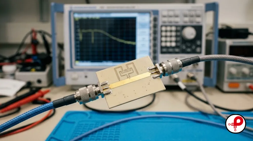
Three properties explain why engineers pay more for a Rogers PCB: the dielectric constant, the dissipation factor, and stability over temperature and frequency.
| Property | What it means | Rogers PCB | Typical FR4 |
|---|---|---|---|
| Dielectric constant (Dk) | How much the material slows a signal | About 2.2 to 3.5, tightly controlled | About 3.9 to 4.7, varies more |
| Dk tolerance | How much Dk varies from sheet to sheet | As tight as ±0.02 to ±0.05 | Often not specified this tightly |
| Dissipation factor (Df) at 10 GHz | How much signal turns into heat | About 0.0009 to 0.0037 | About 0.02 to 0.025 |
| Z axis CTE | Expansion through the board thickness | As low as 32 ppm/°C (RO4350B) | About 45 ppm/°C below Tg, much higher above |
| Processing | How easy the board is to make | RO4000 is like FR4, PTFE is harder | Easiest and cheapest |
Rogers values come from the official Rogers product pages linked below. FR4 values come from Wikipedia’s FR4 entry and the Isola 370HR datasheet.
Low and Stable Dielectric Constant
The dielectric constant sets the width of a 50 ohm trace and the speed of the signal. On a Rogers PCB, Dk is not only lower, it is also specified with a tight tolerance. RO4350B, for instance, is listed at 3.48 ± 0.05.
That tight tolerance is the real advantage. Filters, couplers, antennas and matching networks depend on exact electrical lengths. If Dk shifts from batch to batch, the circuit shifts frequency. Our microstrip impedance calculator shows how strongly Dk affects trace width.
Very Low Dissipation Factor
The dissipation factor, also called loss tangent, measures how much of the signal is lost as heat inside the dielectric. This is where a Rogers PCB pulls far ahead of FR4.
At 10 GHz, Rogers lists RO4350B at a Df of 0.0037. The Isola 370HR FR4 datasheet lists 0.0250 at the same frequency. That means RO4350B has about one seventh of the dielectric loss of this high quality FR4. RT/duroid 5880, at 0.0009, has roughly one twenty eighth.
Lower loss means more of your transmitted power reaches the antenna, receivers stay more sensitive, and long high speed traces keep their shape. Our signal integrity PCB design guide explains how loss adds up along a channel.
Thermal and Mechanical Stability
Many Rogers PCB materials also handle heat well. RO4350B has a low Z axis expansion of 32 ppm/°C, which helps plated through holes survive temperature cycling. Ceramic filled materials also tend to hold their Dk steady as temperature changes, which keeps RF circuits tuned in hot or cold environments.
For power amplifiers and dense RF modules, combine the right laminate with good copper planes and thermal vias. Our thermal management PCB design guide covers those techniques.
7 Best Rogers PCB Materials and Series
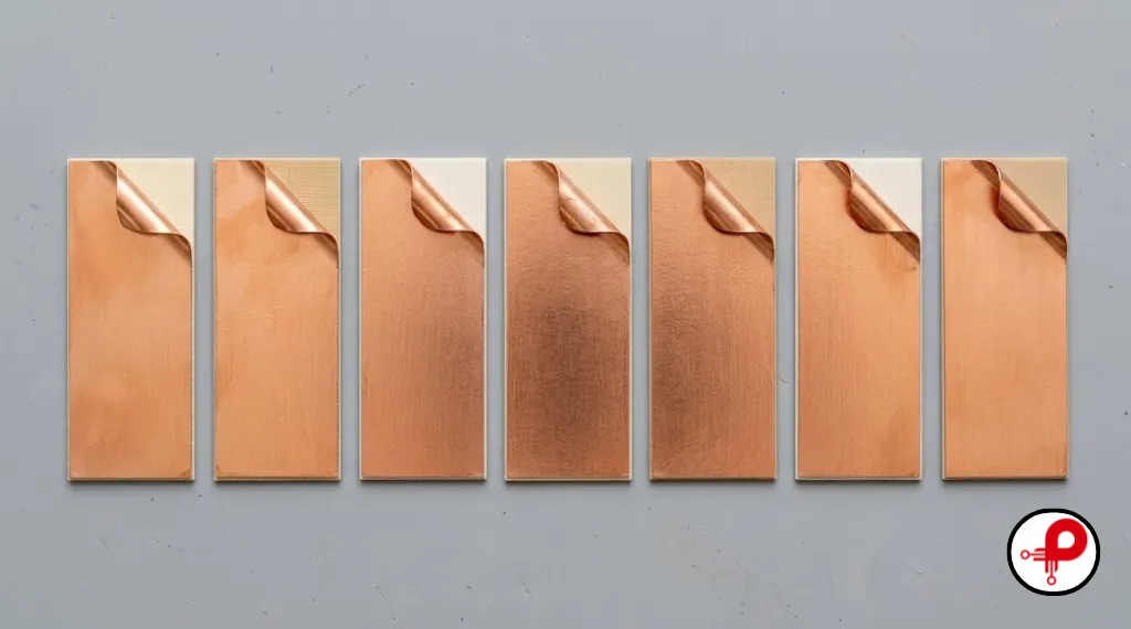
Rogers offers dozens of laminates, but most designs use a small set of proven materials. The four below have values taken directly from the official Rogers product pages.
| Material | Base type | Dk | Df at 10 GHz | Best for |
|---|---|---|---|---|
| RO4003C | Hydrocarbon ceramic, woven glass | 3.38 ± 0.05 | 0.0027 | Low cost RF, LNAs, general microwave |
| RO4350B | Hydrocarbon ceramic, woven glass | 3.48 ± 0.05 | 0.0037 | Power amplifiers, base stations, UL 94 V0 designs |
| RO3003 | Ceramic filled PTFE | 3.00 ± 0.04 | 0.0010 | Millimeter wave, automotive radar |
| RT/duroid 5880 | Glass microfiber PTFE | 2.20 ± 0.02 | 0.0009 | Lowest loss antennas, aerospace |
RO4003C and RO4350B (RO4000 Series)
The RO4000 series is the most popular choice for a first Rogers PCB. Rogers describes these materials as woven glass reinforced hydrocarbon ceramics with electrical performance close to PTFE and the manufacturability of epoxy glass.
The key benefit is processing. According to Rogers, RO4350B processes like FR4 at lower fabrication cost than traditional microwave laminates and does not need the special hole treatments that PTFE needs.
RO4003C has slightly lower loss, with a Df of 0.0027, and a Z axis CTE of 46 ppm/°C. It is a strong choice for low noise amplifiers and passive RF circuits.
RO4350B adds a UL 94 V0 flame rating and a lower Z axis CTE of 32 ppm/°C. That makes it the usual pick for power amplifiers, active antennas and products that need a flame rating.
RO3003 (RO3000 Series)
RO3003 is a ceramic filled PTFE laminate with a Dk of 3.00 and a Df of 0.0010 at 10 GHz. Its very low loss and stable Dk make it a favorite for millimeter wave designs, including 77 GHz automotive radar sensors.
Because it is PTFE based, it needs a fabricator experienced with PTFE drilling, hole preparation and lamination.
RT/duroid 5880
RT/duroid 5880 is one of the lowest loss Rogers PCB materials, with a Dk of 2.20 and a Df of just 0.0009 at 10 GHz. Its low Dk allows wider traces for the same impedance, which reduces conductor loss.
It is widely used in microwave antennas, satellite links, military radar and test equipment. It is softer and more expensive than RO4000 materials, so designers usually reserve it for the circuits that truly need it.
TMM, Kappa and Other Rogers Series
Beyond these four, Rogers offers several other families:
Advanced RF & Microwave Materials
TMM Series
Thermoset microwave materials with ceramic filler, used where very stable Dk over temperature is needed.
Kappa 438
A lower cost laminate designed to bridge the gap between FR4 and premium RF materials.
RO4835 and RO4730G3
RO4000 variants engineered for improved oxidation resistance and advanced antenna designs.
CuClad, DiClad and IsoClad
PTFE based laminates, originally from Arlon, extensively used in demanding military and aerospace work.
Always check the current datasheet on the Rogers website for exact values before using any of these in a design.
Rogers PCB vs FR4
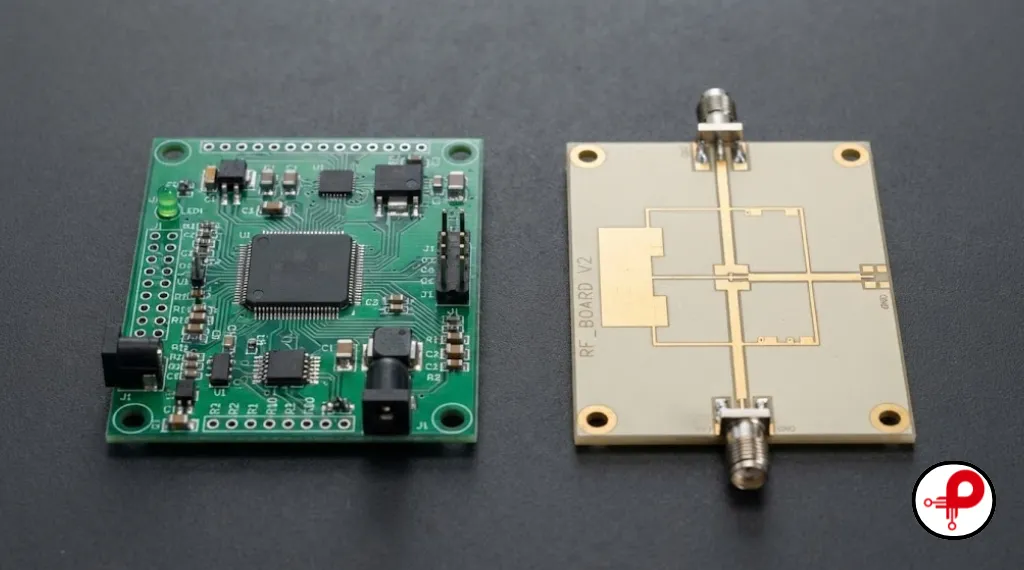
The Rogers PCB vs FR4 question comes down to frequency, loss budget and cost. FR4 is the right choice for most boards. A Rogers PCB becomes worth it when the signal frequency and the cost of losing signal both rise.
| Factor | FR4 | Rogers PCB (RO4350B example) |
|---|---|---|
| Base material | Woven glass epoxy | Hydrocarbon ceramic, woven glass |
| Dk at 10 GHz | About 3.9 to 4.4 | 3.48 ± 0.05 |
| Df at 10 GHz | About 0.02 to 0.025 | 0.0037 |
| Dk stability | Varies with frequency and batch | Tightly controlled |
| Z axis CTE | About 45 ppm/°C below Tg | 32 ppm/°C |
| Fabrication | Standard, every fab | Like FR4 for RO4000; PTFE needs specialist fabs |
| Material cost | Lowest | Several times higher |
| Typical frequency | Up to a few GHz with short traces | Several GHz to millimeter wave |
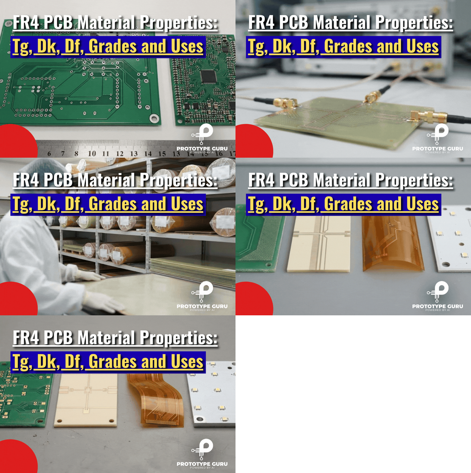
FR4 values come from the Isola 370HR datasheet and the Wikipedia FR4 entry. For a full look at FR4, read our guide to FR4 PCB material properties.
Electrical Performance
The biggest difference is loss. With a Df around seven times lower, a Rogers PCB delivers more power to the antenna, keeps receivers sensitive, and holds the shape of fast digital edges over longer traces.
Dk stability matters just as much. On FR4, Dk changes with frequency, resin content and glass style, so an RF filter may land at a different frequency than simulated. On a Rogers PCB, the simulation and the real board agree much more closely.
Thermal and Mechanical Differences
Rogers materials such as RO4350B expand less through the board thickness than standard FR4 does, especially at soldering temperatures. That improves plated via reliability in boards that see many thermal cycles.
PTFE based Rogers laminates are softer than FR4. They can bend more easily and need careful handling, which is one reason they are often combined with FR4 in hybrid boards.
Rogers PCB vs FR4 Cost
A Rogers PCB costs more for two reasons. The laminate itself is several times the price of FR4, and PTFE based materials need extra fabrication steps such as special hole preparation.
The exact price gap depends on the material, panel size, layer count and fabricator, so always get a quote. RO4000 materials are usually the most affordable entry point, because they process like FR4. A hybrid stackup, explained below, can cut cost further.
When FR4 Is Still Enough
FR4 is often good enough for Bluetooth, WiFi and other designs around 2.4 GHz, as long as RF traces stay short and impedance is controlled. Many commercial wireless modules use FR4 for exactly this reason. Our guides to 2.4 GHz PCB antenna design and building a Bluetooth device show how.
A good way to decide is to simulate the critical RF path on both materials. If FR4 meets your loss, impedance and frequency targets with some margin, there is little reason to pay more. If the FR4 version only passes on paper, or fails across temperature, the extra cost of Rogers material is usually cheaper than a redesign after launch.
Many teams also start with FR4 for an early proof of concept, then move the RF section to Rogers material for the production version once the circuit is proven. This keeps prototype costs low while still giving the final product the performance it needs.
Consider a Rogers PCB when frequencies climb well above a few GHz, when traces are long, when you need predictable filters and antennas, or when your link budget leaves no room for extra loss.
A Simple Loss Example
A quick rule of thumb helps here. Dielectric loss in a transmission line rises in proportion to frequency, to the square root of Dk, and to Df. So if you keep frequency and trace length the same, the material with the lower Df × √Dk loses less.
For FR4 at 10 GHz, using the Isola 370HR values (Dk 3.92, Df 0.025), that product is about 0.049. For RO4350B (Dk 3.48, Df 0.0037) it is about 0.0069. In other words, the dielectric part of the loss on RO4350B is roughly one seventh of the loss on this FR4.
Conductor loss from the copper adds to this on both materials, so real boards will not show the full sevenfold difference. Even so, the gap is large enough to decide many RF designs. On a long feed line at 10 GHz, it can mean the difference between meeting and missing a link budget.
Moisture and Environmental Stability
Moisture is another quiet difference. Water has a very high dielectric constant, so any moisture a laminate absorbs raises its Dk and its loss. PTFE based Rogers laminates absorb very little moisture, which keeps their electrical properties steady in humid climates.
This matters for outdoor equipment such as base station antennas, satellite terminals and automotive radar, which face rain, heat and humidity for years. Always check the moisture absorption value on the datasheet of the exact material you choose.
Rogers PCB Applications
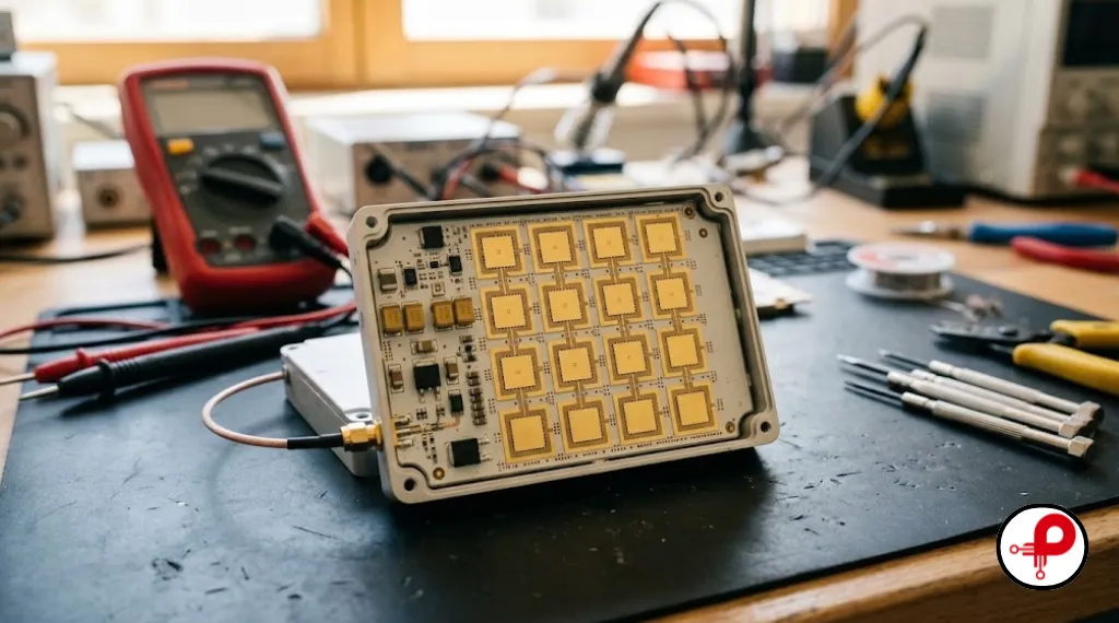
A Rogers PCB shows up wherever RF performance, stability and low loss are worth the extra cost. The most common applications include:
5G and Wireless Infrastructure
Base station antennas, small cells, and power amplifiers, where RO4000 materials balance performance and cost.
Automotive Radar
24 GHz and 77 GHz radar sensors for driver assistance, often built on ceramic-filled PTFE such as RO3003.
Satellite and Aerospace
Satellite communication terminals, phased array antennas, and avionics, where low-loss PTFE laminates such as RT/duroid 5880 excel.
Military and Defence Radar
High-reliability microwave modules engineered to perform dependably across wide temperature ranges.
Power Amplifiers
RF power stages that demand low insertion loss and excellent heat handling. Our dBm to watts converter helps when you size these stages.
Antennas and Passive RF Circuits
Patch antennas, filters, couplers, and power dividers that rely heavily on exact and stable dielectric constant (Dk).
Test and Measurement
Instruments and fixtures where overall measurement accuracy depends directly on stable, high-grade materials.
Across all of these markets, the pattern is the same. The higher the frequency and the tighter the performance target, the more likely the board uses Rogers material on at least one layer. Lower frequency control circuits on the same product often stay on FR4.
For link budgets, our free space path loss calculator shows why every decibel saved on the board counts. Lower board loss can mean longer range or lower transmit power.
Hybrid Rogers PCB Stackups
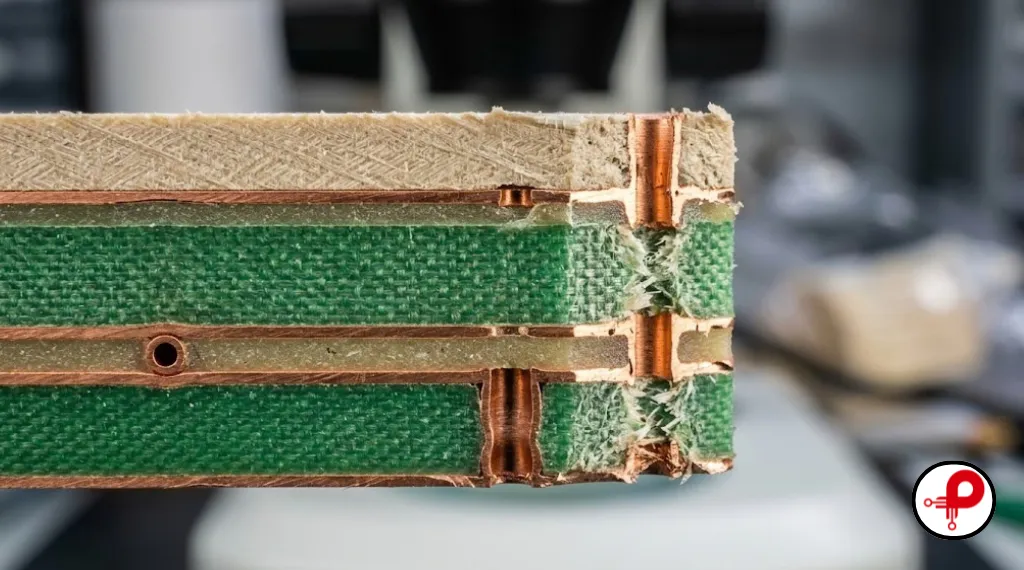
A hybrid stackup combines Rogers and FR4 layers in the same multilayer board. The RF signals run on a Rogers layer, while power, ground, control and digital signals use cheaper FR4 layers.
Why Mix Rogers and FR4
Hybrid boards give you most of the RF benefit of a Rogers PCB at a lower total cost. A typical example is a four layer board with RO4350B as the top dielectric, under the RF traces and antenna, and FR4 for the inner and bottom layers.
The benefits include:
- Lower material cost than an all Rogers board
- Better mechanical strength from the FR4 layers
- Easy routing of digital and power circuits on standard material
- RF performance where it actually matters
Design and Fabrication Tips for Hybrid Boards
Hybrid stackups need extra care, because the two materials expand and cure differently:
- Keep the stackup symmetric wherever possible to reduce warpage.
- Ask the fabricator first. Confirm that they have built your exact Rogers and FR4 combination before you finalize the design.
- Use the fabricator’s real Dk values for each layer when you calculate impedance.
- Watch via reliability. Different Z axis expansion rates stress plated holes, so follow good via design practice.
- Specify the material clearly on the fabrication drawing, with the exact Rogers part number and thickness for each layer.
How to Design and Order a Rogers PCB
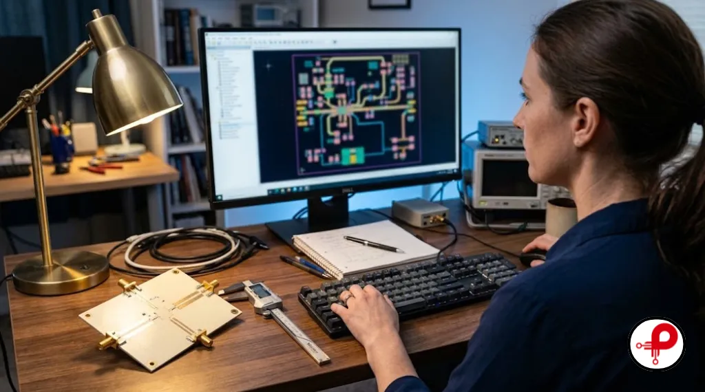
A successful Rogers PCB starts with clear requirements and an experienced fabricator. Use this seven step checklist:
- Define frequency and loss budget. Write down the highest frequency, trace lengths and the maximum acceptable loss.
- Pick the Dk. Lower Dk gives wider traces and lower conductor loss, while higher Dk makes circuits smaller.
- Choose the material family. Start with RO4003C or RO4350B for cost and ease of fabrication. Move to RO3003 or RT/duroid 5880 when loss limits are very tight.
- Select thickness and copper. Thin dielectrics help impedance control, and smooth copper reduces loss at high frequencies. Our PCB thickness guide covers standard options.
- Calculate impedance with real values. Use the design Dk from the Rogers datasheet, then confirm it with the fabricator’s stackup.
- Check fabricator capability. Ask about PTFE experience, hybrid stackups, surface finishes and stock of your chosen laminate.
- Balance cost. Consider a hybrid stackup, and use Rogers only on the layers that carry RF signals.
For general layout rules, also review our circuit board design rules and the most common PCB design mistakes.
Copper Foil and Surface Finish for RF Boards
At high frequencies, current crowds into the outer surface of the copper, an effect called skin effect. Rough copper makes that path longer, which adds loss. Rogers offers many laminates with smoother copper foil options for this reason.
Surface finish matters too. Electroless nickel under gold (ENIG) is common, but the nickel layer can add loss at very high frequencies. Immersion silver or ENEPIG are often preferred for RF boards. Discuss the finish with your fabricator before you place the order.
Common Rogers PCB Design Mistakes
Avoid these errors that often cost a second prototype run:
- Using the process Dk instead of the design Dk. Rogers datasheets list both, and the design Dk is the one to use for impedance and circuit models.
- Ignoring copper roughness. Rough copper can add more loss than the dielectric at millimeter wave frequencies.
- Choosing a PTFE laminate when RO4000 would do. This adds cost and lead time without a real benefit.
- Skipping the fabricator check. Not every fab stocks every Rogers material or builds hybrid boards.
- Forgetting thermal design. Power amplifiers on any laminate still need good copper planes and thermal vias.
Fabrication Challenges
RO4000 materials process much like FR4, which is a major reason for their popularity. PTFE based Rogers materials are more demanding:
- Drilling: soft PTFE can smear inside holes, so fabricators adjust drill speeds and tools.
- Hole preparation: PTFE needs special surface treatment before copper plating so the plating sticks to the hole wall.
- Lamination: PTFE and hybrid boards need tightly controlled press cycles.
- Handling: soft laminates can dent or bend, so panels need careful handling.
These steps add cost and lead time, so request a quote early. Our overview of the PCB manufacturing process explains where each step fits.
FAQ About Rogers PCB
1. What is Rogers PCB material?
↑It includes hydrocarbon ceramic laminates such as RO4350B and PTFE based laminates such as RO3003 and RT/duroid 5880. These materials offer a low, stable dielectric constant and very low signal loss.
2. Who is the manufacturer of Rogers PCB materials?
↓Independent PCB fabricators then use those laminates to build finished Rogers PCBs.
3. What are the key differences between Rogers and FR4 PCBs?
↓FR4 is much cheaper and easier to fabricate, and it is fine for most designs below a few GHz.
4. What is duroid material?
↓RT/duroid 5880 has a Dk of 2.20 and a Df of 0.0009 at 10 GHz, making it one of the lowest loss PCB materials available.
5. What material is PCB made of?
↓High frequency boards use special laminates such as Rogers materials, flexible boards use polyimide, and high power LED boards often use an aluminum core.
6. What are the most popular Rogers PCB materials?
↓7. Can Rogers materials be mixed with FR4 in a hybrid PCB stack-up?
↓8. How do you choose between RO4003C and RO4350B?
↓Key Takeaways
A Rogers PCB is the right tool when signal frequency, loss and predictable performance matter more than material cost. Start with RO4003C or RO4350B for most RF work, move to RO3003 or RT/duroid 5880 for millimeter wave or the lowest loss designs, and use a hybrid stackup to keep costs under control.
For everything else, standard FR4 remains the sensible choice. Choose the material from verified datasheet values, confirm the stackup with your fabricator, and your Rogers PCB will perform just as your simulation predicts. To keep the rest of your RF design clean, read our EMI and EMC PCB design guide as well.