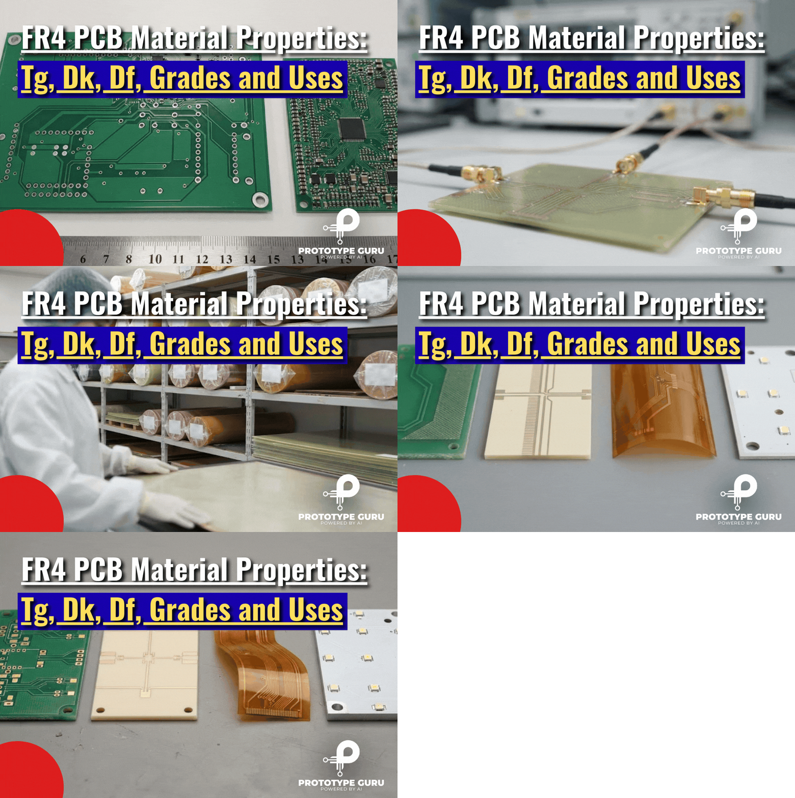











FR4 PCB material properties decide how your circuit board handles heat, signals and mechanical stress. For a quick answer, a standard FR4 laminate usually has a glass transition temperature (Tg) of about 130 to 140 °C, a dielectric constant (Dk) of roughly 4.2 to 4.5 at 1 GHz, and a dissipation factor (Df) of about 0.015 to 0.025.
Those numbers are only a starting point. FR4 is a family of materials, not one material, and two laminates that are both called “FR4” can behave very differently in a reflow oven or a 5 GHz channel.
This guide explains every property that matters, with real datasheet values and the test conditions behind them. You will also find the IPC 4101 grades, a comparison with G10, Rogers and aluminum, the seven best uses of FR4, and a simple checklist for choosing the right laminate.
What Is FR4 PCB Material?
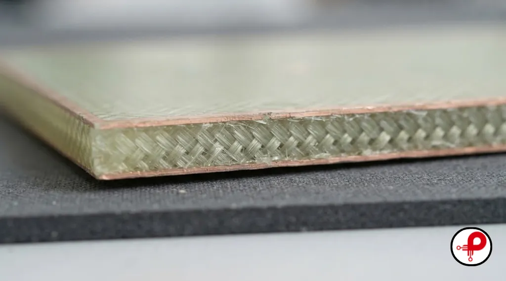
FR4 is a glass reinforced epoxy laminate. It is made from woven fiberglass cloth soaked in epoxy resin, then pressed and cured into rigid sheets. It is the base material of most rigid printed circuit boards made today.
The fiberglass gives the board strength and keeps it dimensionally stable, and it shapes many FR4 PCB material properties such as stiffness and X and Y expansion. The epoxy resin binds the glass together and insulates the copper layers from each other.
What FR4 Stands For
The name is a grade designation created by NEMA (the National Electrical Manufacturers Association) in 1968 and defined in the NEMA LI 1 standard. “FR” stands for flame retardant, and “4” identifies the woven glass epoxy grade.
There is an important detail here. According to Wikipedia’s FR4 entry, the FR label alone does not prove the material meets UL 94 V0. The laminate has to be tested to the UL 94 vertical flame test before it can claim that rating.
Laminate, Prepreg and Copper Clad Core
FR4 reaches your board in two forms:
- Core (laminate): fully cured FR4 with copper foil bonded to one or both sides. This is the copper clad laminate you see in a stackup.
- Prepreg: glass cloth filled with partly cured resin. It bonds the cores and outer copper layers together during lamination.
Both forms share the same basic FR4 PCB material properties, but prepreg has more resin, so its Dk is usually a little lower than that of a core of the same family. If you want to see how these layers come together, read our guide to the PCB manufacturing process.
Is FR4 Plastic?
Yes, in a broad sense. FR4 is a thermoset composite, which means it is a plastic (epoxy) reinforced with glass fiber. Unlike common thermoplastics, it does not melt and reflow when heated. This thermoset nature explains several FR4 PCB material properties, including its good dimensional stability during soldering. It softens above its Tg and eventually decomposes at very high temperatures.
Key FR4 PCB Material Properties at a Glance
The table below brings the most important FR4 PCB material properties into one place. It shows typical values, the units, and why each one matters for your design.
| Property | Typical value | Unit | Why it matters |
|---|---|---|---|
| Glass transition temperature (Tg) | 130 to 140 (standard), 150 to 160 (mid), 170 or more (high Tg) | °C | Expansion and reliability during soldering |
| Decomposition temperature (Td) | About 310 to 340, grade dependent | °C | Resistance to lead free reflow |
| Dielectric constant (Dk) | About 3.8 to 4.8, often about 4.2 to 4.4 at 1 GHz | none | Impedance and signal speed |
| Dissipation factor (Df) | About 0.015 to 0.025 at 1 GHz | none | Signal loss at high frequency |
| Dielectric strength | About 20 | MV/m | Insulation between conductors |
| Z axis CTE below Tg | About 45 to 70 | ppm/°C | Stress on plated holes |
| Thermal conductivity, through plane | About 0.29 | W/(m·K) | Heat flow out of components |
| Density | About 1.85 | g/cm³ | Board weight |
| Water absorption | Below 0.10 | % | Electrical stability in humidity |
| Flammability | UL 94 V0 (when tested) | rating | Fire safety compliance |
These values combine the example property table published on Wikipedia with real datasheets such as Isola 370HR. Treat them as planning figures. The exact numbers for your board always come from the datasheet of the laminate your fabricator actually uses.
Electrical FR4 PCB Material Properties
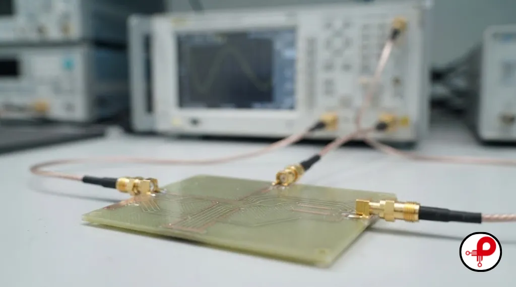
The electrical FR4 PCB material properties control how fast signals travel, how much energy they lose, and how well the copper layers stay insulated from one another.
FR4 Dielectric Constant (Dk)
The dielectric constant, also called relative permittivity, is the most quoted of all FR4 PCB material properties. It tells you how much the material slows down an electrical signal compared with a vacuum. A higher Dk means slower signals and a narrower trace for the same impedance.
The FR4 dielectric constant is not fixed. It changes with resin content, glass style, frequency and the test method. That is why you will see quoted ranges from about 3.8 to 4.8, as Altium’s FR4 guide also points out.
Here is a real example from the Isola 370HR datasheet, a widely used high Tg FR4:
| Frequency | Dk | Df |
|---|---|---|
| 100 MHz | 4.24 | 0.0150 |
| 1 GHz | 4.17 | 0.0161 |
| 2 GHz | 4.04 | 0.0210 |
| 5 GHz | 3.92 | 0.0250 |
| 10 GHz | 3.92 | 0.0250 |
Notice two trends. Dk falls slightly as frequency rises, and Df rises. Both trends are typical of epoxy glass laminates.
For impedance work, always use the Dk at your signal’s operating frequency, not the 1 MHz value printed on older datasheets. You can check your trace geometry with our microstrip impedance calculator.
How Glass Weave Changes Dk
Glass has a Dk around 6, while epoxy resin is closer to 3. FR4 sits between the two, depending on the mix.
Thin prepregs such as style 106 or 1080 contain a lot of resin, so their Dk is lower. Heavy glass styles such as 7628 contain more glass, so their Dk is higher. A trace running along a glass bundle can see a slightly different Dk than a trace running over a resin gap. This “fiber weave effect” can cause skew in fast differential pairs.
Dissipation Factor (Df) and Signal Loss
The dissipation factor, or loss tangent, measures how much signal energy the material turns into heat. Standard FR4 usually sits between about 0.015 and 0.025.
Among the electrical FR4 PCB material properties, Df is the one that limits high speed performance. At low frequencies this loss hardly matters. As data rates climb into several gigabits per second, the loss adds up over long traces, and the signal arrives smaller and slower to rise. That is the main reason designers move to low loss laminates for long, fast channels.
There is no single frequency where FR4 suddenly stops working. The real limit depends on trace length, data rate, copper roughness and your loss budget. Our signal integrity PCB design guide covers how to build that budget.
Dielectric Strength and Insulation
FR4 has a dielectric strength of about 20 MV/m, which equals 20 kV per millimetre. In everyday terms, it insulates very well, which is why it is also used for electrical insulators, spacers and terminal boards.
In real boards, spacing rules are usually set by creepage and clearance standards rather than by the raw dielectric strength. For high voltage designs, also check the comparative tracking index (CTI) of the laminate.
Thermal FR4 PCB Material Properties
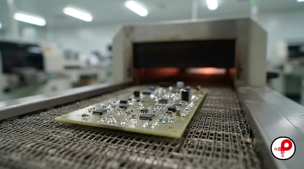
Thermal FR4 PCB material properties decide whether your board survives soldering and years of heating and cooling in the field. They are also where most “FR4 failed” stories begin.
Glass Transition Temperature (Tg)
The glass transition temperature is the most important of the thermal FR4 PCB material properties. It is the point where the epoxy changes from a hard, glassy state to a softer, rubbery state. Above Tg, the material expands much faster, especially through its thickness.
FR4 grades are usually grouped like this:
Standard Tg
About 130 to 140 °C
Mid Tg
About 150 to 160 °C
High Tg
170 °C and above
Because these grades are defined by Tg, this single value is often the first of the FR4 PCB material properties a fabricator asks about. Tg is measured with test methods from the IPC TM 650 manual, such as DSC (differential scanning calorimetry), DMA or TMA. Each method can give a slightly different number, so compare like with like.
Decomposition Temperature (Td), T260 and T288
Td is the temperature where the resin starts to break down. It is normally defined as the point where the material has lost 5% of its weight. Isola 370HR, for example, lists a Td of 340 °C.
Td matters more than Tg for lead free soldering, because lead free reflow peaks around 245 to 260 °C. A laminate with a low Td can lose resin strength and delaminate after several passes.
Two more numbers help here. T260 and T288 measure how many minutes the laminate survives at 260 °C or 288 °C before it delaminates. Isola 370HR lists 60 minutes at 260 °C and 30 minutes at 288 °C. Higher is better for boards that see many reflow or rework cycles.
CTE and Z Axis Expansion
The coefficient of thermal expansion (CTE) tells you how much the material grows when it heats up. In the X and Y directions, the glass keeps FR4 close to copper, at about 12 to 14 ppm/°C.
The Z axis, through the board thickness, is the weak point. Isola 370HR lists 45 ppm/°C below Tg but 230 ppm/°C above Tg, with a total expansion of 2.8% from 50 to 260 °C. Copper expands only about 17 ppm/°C.
That mismatch pulls on plated through holes and vias during every heat cycle. For reliability, Z axis CTE is one of the FR4 PCB material properties that deserves the most attention. Over time it can crack barrels and pads, which is why thick, multilayer boards need a laminate with low Z axis expansion. Our PCB via design guide explains how via geometry adds to this risk.
Thermal Conductivity
FR4 is a poor heat conductor. Its thermal conductivity is about 0.29 W/(m·K) through the board and about 0.81 W/(m·K) along the board, according to the example values on Wikipedia.
That is hundreds of times lower than copper, so thermal conductivity is one of the weaker FR4 PCB material properties. In practice, heat in an FR4 board moves through copper planes and thermal vias, not through the laminate itself. Our thermal management PCB design guide shows how to use copper to move heat away from hot parts.
How Hot Can FR4 Get?
There is no single answer, because three different temperatures are often confused:
| Property / Parameter | What it means | Example (Isola 370HR) |
|---|---|---|
| RTI (UL 796) | Safe long term operating limit | 130 °C |
| Tg | Resin softens and expansion speeds up | 180 °C |
| Td | Resin starts to decompose | 340 °C |
For continuous operation, stay below the laminate’s relative thermal index (RTI) and keep a margin below Tg. Short excursions, such as reflow, can go higher, but only for minutes.
Mechanical and Physical FR4 PCB Material Properties
The mechanical FR4 PCB material properties explain why boards stay flat, hold screws and survive drops. The values below are example figures from the Wikipedia property table.
| Property | Example value |
|---|---|
| Density | 1.85 g/cm³ |
| Flexural strength, lengthwise | Above 415 MPa |
| Flexural strength, crosswise | Above 345 MPa |
| Young’s modulus, lengthwise | About 24 GPa |
| Rockwell hardness | 110 (M scale) |
| Water absorption | Below 0.10% |
Of these FR4 PCB material properties, density is the one people search for most. The density of about 1.85 g/cm³ (1,850 kg/m³) is useful when you estimate board weight for drones, wearables or shipping. Low water absorption keeps the dielectric stable in humid conditions, although FR4 is not waterproof. Moisture can still enter through edges and holes, so conformal coating and enclosure design still matter.
Is FR4 Flammable? UL 94 V0 Explained
FR4 is flame retardant, not fireproof. Most FR4 laminates are rated UL 94 V0, which means a vertical test sample stops burning within 10 seconds after the flame is removed, with no flaming drips.
The flame retardant in standard FR4 is usually a bromine compound. Halogen free FR4 uses other chemistry to reach the same rating. Under extreme heat, any FR4 board will still char and smoke.
FR4 Grades and IPC 4101 Slash Sheets
IPC 4101 is the specification for base materials used in rigid and multilayer boards. It sorts laminates into numbered “slash sheets”, and each sheet sets minimum values for properties such as Tg and Td. The official contents are listed in the IPC 4101 table of contents.
This is the most practical way to compare FR4 PCB material properties across brands. If your drawing calls out a slash sheet, any laminate certified to that sheet should be acceptable.
| IPC 4101 slash sheet | Typical description | Tg minimum | Td minimum | Filler |
|---|---|---|---|---|
| /21 | Classic standard FR4 | 110 °C | Not specified | No |
| /101 | Lead free capable, standard Tg | 110 °C | 310 °C | Yes |
| /121 | Lead free capable, standard Tg | 110 °C | 310 °C | No |
| /99 | Lead free capable, mid Tg | 150 °C | 325 °C | Yes |
| /124 | Lead free capable, mid Tg | 150 °C | 325 °C | No |
| /126 | Lead free capable, high Tg | 170 °C | 340 °C | Yes |
| /129 | Lead free capable, high Tg | 170 °C | 340 °C | No |
The Tg and Td minimums follow summaries of IPC 4101 published by fabricators. Always confirm the exact requirements against the current revision of the standard before writing them into a contract.
Standard FR4 vs High Tg FR4
The difference between these two grades comes down to their thermal FR4 PCB material properties. Standard FR4 is the right choice for most simple boards with few reflow cycles and moderate operating temperatures. It is the cheapest and most widely stocked option.
High Tg FR4 is worth the extra cost when you have:
Key Scenarios for High Tg Material
Many layers or thick board
Usually above 1.6 mm, requiring superior dimensional stability under stress.
Lead-free assembly
Designed for multiple reflow or rework passes with higher thermal thresholds.
High operating temperatures
Essential for demanding automotive or heavy industrial equipment environments.
Dense via fields & fine pitch BGAs
Resists delamination and z-axis expansion around high-density component areas.
Remember that high Tg does not automatically mean low loss. Tg is a thermal property, while Dk and Df are electrical properties, and you must check both.
Halogen Free and High CTI FR4
Halogen free FR4 replaces brominated flame retardants to meet environmental or customer requirements. Check that it still meets UL 94 V0 and your thermal needs.
High CTI FR4 resists electrical tracking across the surface. It helps in power supplies and mains powered equipment, where creepage distances are tight. Our surge protection PCB design guide covers related layout rules.
FR4 vs G10, Rogers, Polyimide and Aluminum
Comparing FR4 PCB material properties with other substrates shows where FR4 fits and where it does not.
| Material | Main strength | Main limit | Typical use |
|---|---|---|---|
| Standard FR4 | Low cost, easy to process | Moderate loss, low thermal conductivity | Most digital and control boards |
| High Tg FR4 | Better thermal reliability | Higher cost | Multilayer, automotive, industrial |
| G10 | Similar strength to FR4 | Not flame retardant | Mechanical and insulating parts |
| Rogers RO4350B | Dk 3.48 ± 0.05, Df 0.0037 at 10 GHz | Higher material cost | RF and microwave circuits |
| Polyimide | Flexible, high temperature | Cost and processing | Flex and rigid flex boards |
| Aluminum core (MCPCB) | Much better heat spreading | Usually single layer | LED lighting, power modules |
The Rogers figures come from the Rogers RO4350B product page, which also notes that it processes like FR4 and has a Z axis CTE of 32 ppm/°C. For flexible designs, see our comparison of flex PCB vs rigid PCB. For heat heavy designs, our heat sink design guide explains when a metal core or a heat sink makes more sense than FR4.
FR4 vs G10
G10 and FR4 are both woven glass epoxy laminates and look almost identical. The key difference is that G10 has no flame retardant additive, while FR4 does. Atlas Fibre notes that this is why FR4 replaced G10 for most electrical uses. Never substitute G10 for FR4 on a PCB that needs a UL 94 V0 rating.
What Material Is Equivalent to FR4?
The truest equivalent is another FR4 laminate certified to the same IPC 4101 slash sheet, because the sheet guarantees matching minimum FR4 PCB material properties. Isola, Panasonic, Shengyi, Kingboard and ITEQ all make laminates that meet the common sheets.
If you need a different material altogether, G10 matches its mechanical strength without the flame rating. CEM 3 is a lower cost composite with similar electrical behavior but less strength.
7 Best Uses of FR4 PCB Material
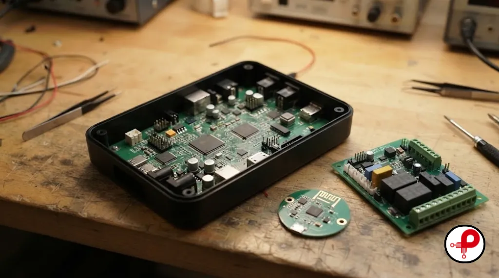
FR4 PCB material properties fit an enormous range of products. These are the seven applications where FR4 shines:
- Consumer electronics: phones, chargers, toys and home appliances, where low cost and easy processing win.
- Microcontroller and embedded boards: development boards, IoT nodes and sensor modules.
- Industrial control: PLC cards, motor controllers and interface boards such as RS485 designs, often on high Tg FR4.
- Computers and networking: motherboards and line cards, using mid loss FR4 grades for faster buses.
- Automotive electronics: body control and infotainment modules on high Tg, high reliability FR4.
- Power supplies: DC DC converters and chargers, sometimes on high CTI FR4. See our DC DC converter PCB design guide.
- Low GHz wireless: Bluetooth and WiFi modules at 2.4 GHz, where short traces keep FR4 losses acceptable. Our 2.4 GHz PCB antenna design guide shows how.
How to Choose the Right FR4 PCB Material Properties
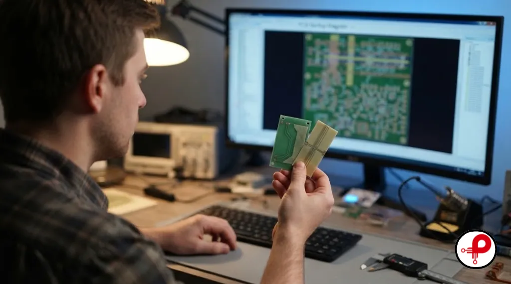
Use this checklist before you release a stackup. It turns the FR4 PCB material properties above into a decision.
- Define the environment. Write down the maximum operating temperature, humidity and any safety standards. These set the minimum FR4 PCB material properties you need.
- Count the thermal cycles. Lead free assembly, double sided reflow and rework all push you toward higher Tg and Td.
- Check the stackup. Thick boards and high layer counts need low Z axis expansion.
- Set your electrical targets. For controlled impedance, get the Dk and Df at your operating frequency from the fabricator.
- Estimate the loss budget. For long, fast links, compare standard, mid loss and low loss grades.
- Name the IPC 4101 slash sheet on your fabrication drawing, rather than just writing “FR4”.
- Approve substitutions carefully. If the fabricator offers another laminate, compare its datasheet before you agree.
For more layout guidance, read our circuit board design rules and design for manufacturing guidelines.
Standard FR4 Thickness Options
The most common finished FR4 board thickness is 1.6 mm (about 0.062 in). Other popular options include 0.8 mm, 1.0 mm, 1.2 mm and 2.0 mm.
Thickness is a stackup choice, not one of the fixed FR4 PCB material properties. Your fabricator builds it from cores and prepregs, so confirm the tolerance with them. Our PCB thickness guide covers the options in detail.
FR4 Material Cost
Standard FR4 is the lowest cost rigid laminate for most boards. High Tg and halogen free grades cost more, and low loss FR4 costs more again. Specialty RF laminates such as Rogers are usually several times the price of standard FR4.
Laminate prices change with copper and glass costs, so always get a current quote. Paying only for the FR4 PCB material properties you truly need is the easiest way to save money. In many designs, using high performance material only on the critical layers keeps costs under control.
FAQ About FR4 PCB Material Properties
1. What is FR4 material in PCB?
↑It forms the insulating base and mechanical support of most rigid circuit boards, with copper foil bonded to its surface.
2. Why is FR4 used in PCB?
↓It also has a huge supply chain, so almost every fabricator stocks it readily.
3. Is FR4 flammable?
↓However, it is not completely fireproof and will char under extreme heat conditions.
4. Is FR4 plastic?
↓It does not melt when heated, but it softens significantly above its glass transition temperature (Tg).
5. What material is equivalent to FR4?
↓G10 is mechanically similar but lacks flame retardancy, whereas CEM 3 functions as a lower-cost alternative.
6. What is the difference between G10 and FR4?
↓FR4 is the required choice for circuit boards that demand a certified UL 94 V0 rating.
7. How hot can FR4 get?
↓It can withstand short reflow soldering peaks around 260 °C, but continuous operation must stay safely below its Tg.
8. What is the standard thickness of FR4 material?
↓Alternative thicknesses such as 0.8, 1.0, 1.2, and 2.0 mm are also widely available.
9. What is the cost of FR4 material?
↓High Tg, halogen-free, and low-loss grades cost more, while specialized RF laminates are significantly more expensive.
Key Takeaways
FR4 PCB material properties are a family of values, not a single number. Start with typical figures for early planning, then pull exact Tg, Td, Dk, Df and CTE values from the datasheet of the laminate you will actually use.
Match Tg and Td to your assembly process, match Dk and Df to your signal speeds, and name an IPC 4101 slash sheet on your drawing. Do that, and FR4 will serve you well on everything from a simple sensor board to a dense multilayer controller. For a broader view of design risks, read our list of common PCB design mistakes.