




The ESP32 pinout on a DevKit board gives you 25 GPIO pins on the 30 pin version and 32 on the 38 pin version, but only about 15 of them are safe for any job. Start with GPIO 4, 13, 16 to 19, 21 to 23, 25 to 27, 32 and 33. GPIO 34 to 39 can only read inputs. GPIO 6 to 11 belong to the flash chip, so leave them alone. And GPIO 0, 2, 5, 12 and 15 decide how the chip boots, which makes them risky for buttons, relays and anything else that pulls the pin HIGH or LOW at reset.
Pick the wrong pin and the symptoms look like a dead board. It resets in a loop, refuses to upload, or your analog sensor goes silent the moment WiFi connects. This guide maps both DevKit layouts first. Then it covers power pins, ADC, DAC, touch, I2C, SPI, UART, PWM and RTC pins, with the pin rules we follow at PrototypeGuru when we lay out custom ESP32 boards. If you haven’t picked a board yet, our ESP32 selection guide helps you choose one first.
ESP32 Pinout Diagram (30 Pin and 38 Pin DevKit)
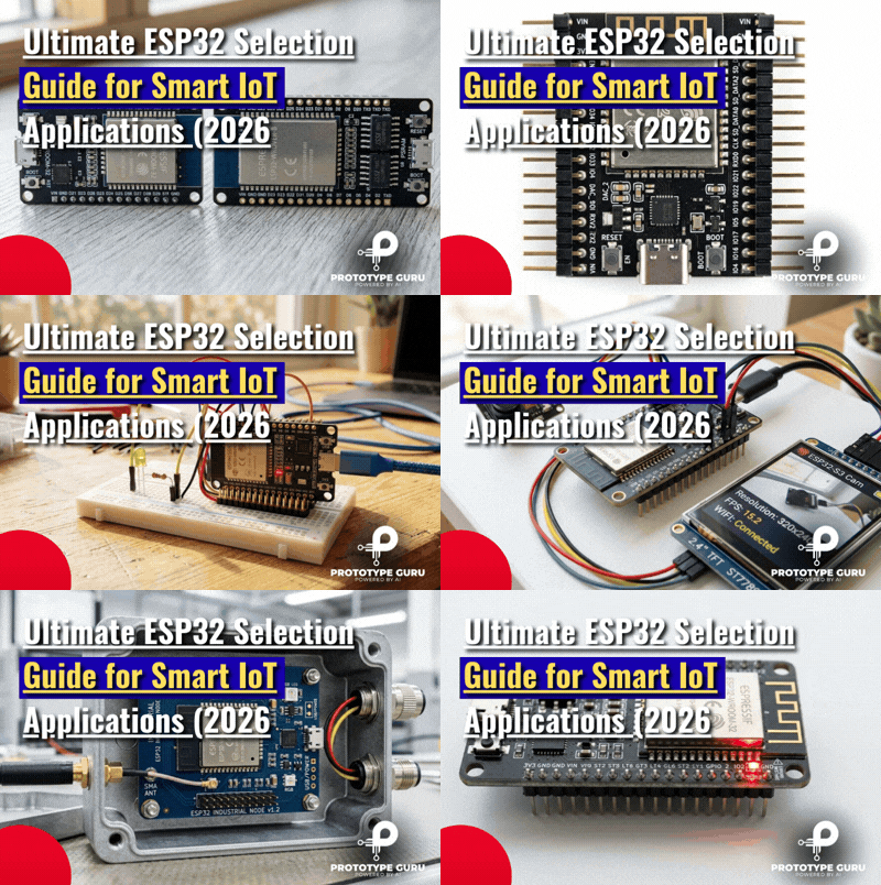
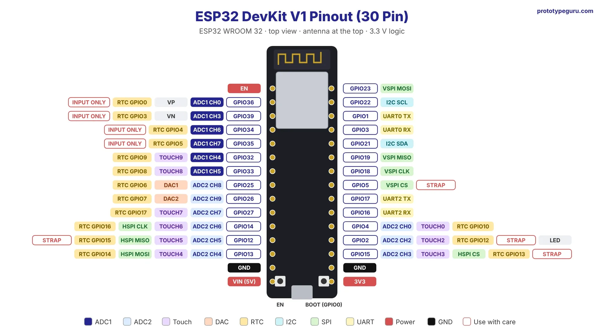
Two board layouts cover most ESP32 boards on the market. Same module, same GPIO numbers. The difference is how many of the chip’s pins the board maker chose to route out to the headers, and that choice decides which pins you can reach without soldering to the module.
Read the label next to each header pin, then match it to the GPIO number in this guide. Some boards print “D23”, others print “23” or “IO23”. They all mean GPIO 23.
ESP32 Pinout 30 Pin (DevKit V1)
The 30 pin board, sold as ESP32 DevKit V1 or DOIT ESP32 DevKit, is the cheapest and most common version. GPIO 0 sits behind the BOOT button. The six flash pins are missing too, and you lose nothing there, since you shouldn’t touch them anyway.
| Left header (top to bottom) | Right header (top to bottom) |
|---|---|
| EN | GPIO 23 |
| GPIO 36 (VP) | GPIO 22 |
| GPIO 39 (VN) | GPIO 1 (TX0) |
| GPIO 34 | GPIO 3 (RX0) |
| GPIO 35 | GPIO 21 |
| GPIO 32 | GPIO 19 |
| GPIO 33 | GPIO 18 |
| GPIO 25 | GPIO 5 |
| GPIO 26 | GPIO 17 (TX2) |
| GPIO 27 | GPIO 16 (RX2) |
| GPIO 14 | GPIO 4 |
| GPIO 12 | GPIO 2 |
| GPIO 13 | GPIO 15 |
| GND | GND |
| VIN | 3V3 |
Pin order can shift between clone makers. Check the silkscreen on your own board before you solder headers or design a carrier PCB around it.
ESP32 Pinout 38 Pin (DevKitC)
The 38 pin layout follows the official Espressif ESP32 DevKitC board. It adds GPIO 0, an extra GND, a 5V pin and the six flash pins labelled CLK, SD0, SD1, SD2, SD3 and CMD.
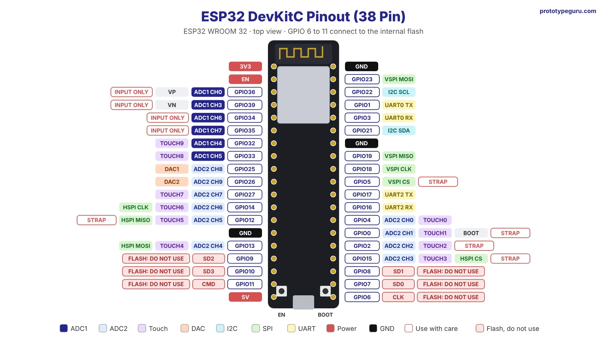
Those six extra pins connect to the SPI flash inside the module, and driving any of them crashes the chip. So you gain one useful pin. GPIO 0. And it’s a strapping pin.
Download the Printable ESP32 Pinout PDF
Keep a copy on your bench. The PDF has both layouts on one A4 page, colour coded by safe, careful and avoid.
[ADD: link to the PDF file after upload]
ESP32 WROOM 32 Pinout and Chip Overview
The ESP32 chip sits inside a metal shielded module called the ESP32 WROOM 32, which also holds a 4 MB flash chip, a 40 MHz crystal and a printed PCB antenna along one short edge. Espressif now ships the WROOM 32E and WROOM 32UE versions. Same pinout. This guide covers all three.
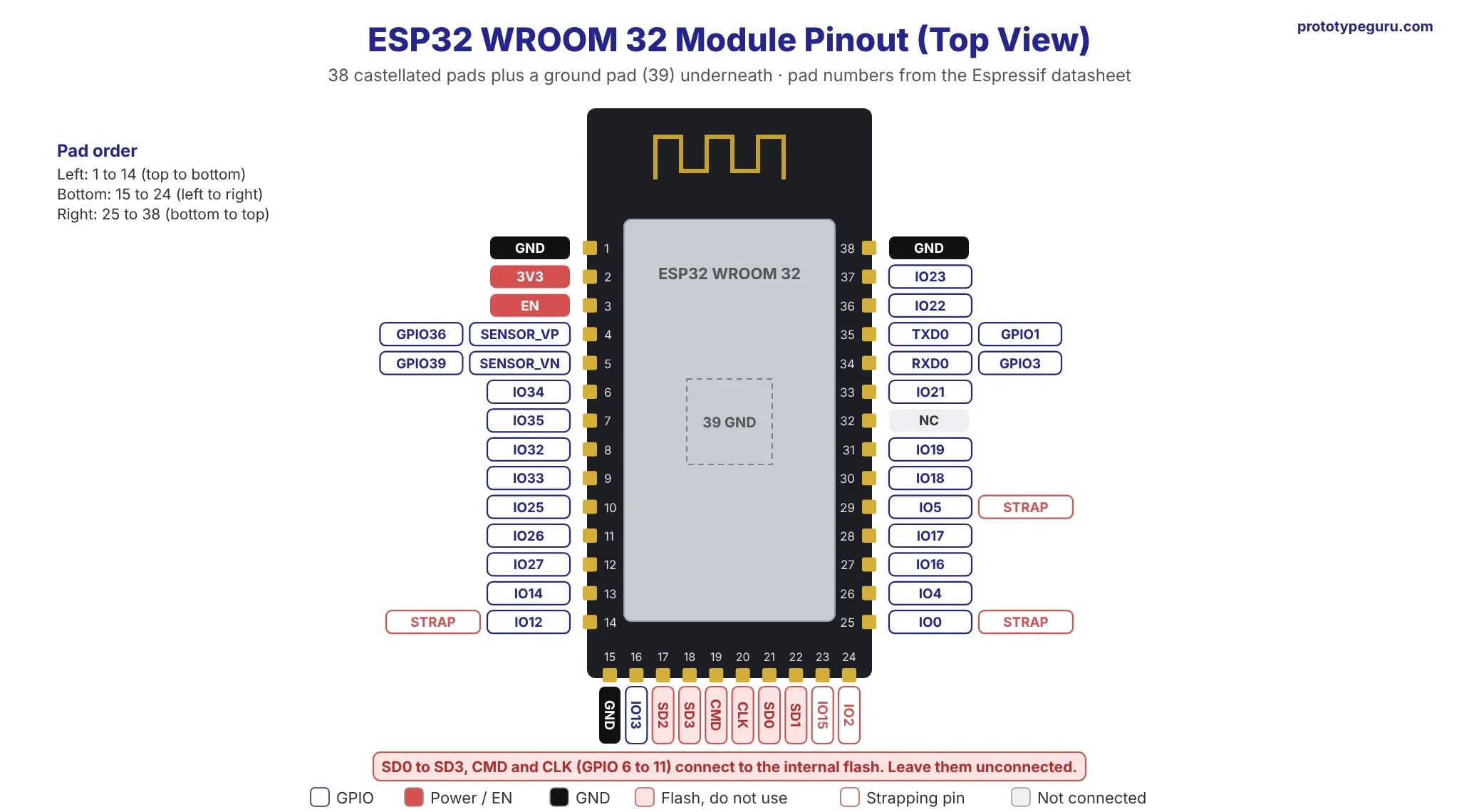
The module has 38 pads along three sides plus a ground pad underneath, and the chip inside has these main features, per the ESP32 datasheet:
| Feature | ESP32 (classic) |
|---|---|
| CPU | Dual core Xtensa LX6, up to 240 MHz |
| SRAM | 520 KB |
| GPIO on the chip | 34 |
| ADC | 18 channels, 12 bit |
| DAC | 2 channels, 8 bit |
| Touch sensors | 10 |
| Wireless | WiFi 802.11 b/g/n and Bluetooth 4.2 (Classic and BLE) |
| Logic level | 3.3 V |
GPIO numbers on the ESP32 skip a few values. GPIO 20, 24 and 28 to 31 don’t exist, and GPIO 37 and 38 stay inside the module with no pad. That gap confuses people coming from Arduino Uno boards, where pin numbers run in order.
Boards sold as NodeMCU 32S use the same chip and module. The rules here apply to them too. People build WiFi sensors, home automation nodes, BLE trackers, data loggers and small web servers with it. Before your first upload, add ESP32 to Arduino IDE with the official board manager URL, and if the board list stays empty after that, our fix for the ESP32 board manager URL not working walks through the usual causes.
ESP32 GPIO Quick Reference: Safe Pins and Pins to Avoid
Save this table. It answers the question behind most ESP32 pinout searches, which is “can I use this pin for my project?”
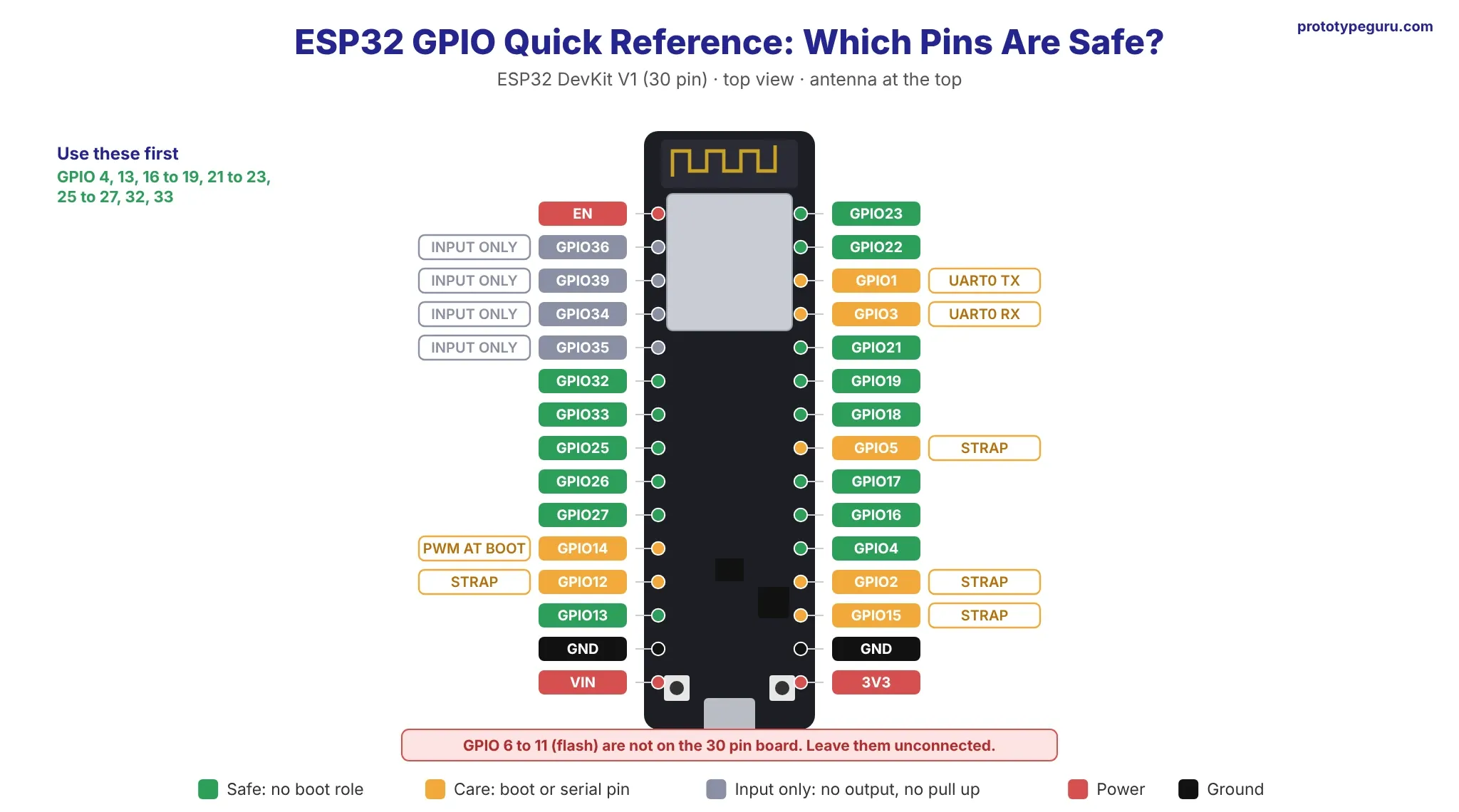
| GPIO | Status | Input | Output | Notes |
|---|---|---|---|---|
| 0 | Careful | Yes | Yes | Strapping pin. LOW at boot enters download mode. BOOT button. ADC2, Touch 1 |
| 1 | Careful | No | Yes | UART0 TX. Sends debug text at boot |
| 2 | Careful | Yes | Yes | Strapping pin. Onboard LED on many DevKit V1 boards. ADC2, Touch 2 |
| 3 | Careful | Yes | No | UART0 RX. HIGH at boot |
| 4 | Safe | Yes | Yes | ADC2, Touch 0 |
| 5 | Careful | Yes | Yes | Strapping pin. Outputs a PWM signal at boot. VSPI CS |
| 6 to 11 | Avoid | No | No | Connected to the SPI flash |
| 12 | Careful | Yes | Yes | Strapping pin. HIGH at boot breaks booting. ADC2, Touch 5 |
| 13 | Safe | Yes | Yes | ADC2, Touch 4, HSPI MOSI |
| 14 | Careful | Yes | Yes | Outputs a PWM signal at boot. ADC2, Touch 6 |
| 15 | Careful | Yes | Yes | Strapping pin. HIGH at boot. ADC2, Touch 3 |
| 16, 17 | Safe | Yes | Yes | UART2. Used by PSRAM on WROVER modules |
| 18, 19 | Safe | Yes | Yes | VSPI CLK and MISO |
| 21, 22 | Safe | Yes | Yes | Default I2C SDA and SCL |
| 23 | Safe | Yes | Yes | VSPI MOSI |
| 25, 26 | Safe | Yes | Yes | DAC 1 and DAC 2, ADC2 |
| 27 | Safe | Yes | Yes | ADC2, Touch 7 |
| 32, 33 | Safe | Yes | Yes | ADC1, Touch 9 and Touch 8 |
| 34, 35, 36, 39 | Input only | Yes | No | ADC1. No internal pull up or pull down |
“Safe” here means the pin has no boot role and no hidden connection, though it still runs at 3.3 V logic and carries the current limits covered in the power section below.
Input Only Pins (GPIO 34 to 39)
GPIO 34, 35, 36 and 39 can read signals but can’t drive anything. No internal pull ups either. Set INPUT_PULLUP on them and nothing happens, so a button on GPIO 34 needs an external 10 kΩ resistor, or the pin floats and reads random values all day.
These four pins suit analog sensors well, because they sit on ADC1. Boards label GPIO 36 as VP and GPIO 39 as VN, a leftover from an amplifier feature that Espressif dropped from later documentation.
SPI Flash Pins (GPIO 6 to 11)
GPIO 6 to 11 connect to the flash chip that stores your program. The 38 pin board breaks them out as CLK, SD0, SD1, SD2, SD3 and CMD. Drive one of them and the chip loses its link to its own code, so it crashes or resets. Treat them as reserved.
Strapping Pins and Pins HIGH at Boot
At power up, the ESP32 reads five strapping pins to decide how it should start, and the ESP32 datasheet lists them as GPIO 0, 2, 5, 12 and 15.
| Strapping pin | Default | Effect at boot |
|---|---|---|
| GPIO 0 | Pull up | LOW enters download mode for flashing |
| GPIO 2 | Pull down | Must be LOW or floating to enter download mode |
| GPIO 5 | Pull up | Sets SDIO slave timing |
| GPIO 12 (MTDI) | Pull down | HIGH sets flash voltage to 1.8 V, which stops a 3.3 V flash module from booting |
| GPIO 15 (MTDO) | Pull up | LOW silences the boot log on UART0 |
GPIO 12 causes the most grief. Hang a sensor or a pull up resistor on it and the board stops booting with a flash read error. Some pins also change state for a moment at boot. GPIO 1, 3, 5, 14 and 15 go HIGH or output PWM during startup, so a relay on one of them can click each time you power the board.
You can use strapping pins once the chip has booted. Keep anything connected to them from pulling the pin the wrong way during reset.
ESP32 Power Pins: 3V3, VIN, GND and EN
The power pins confuse beginners more than any GPIO, and a mistake here can kill the board.
| Pin | Function |
|---|---|
| 3V3 | Output from the onboard 3.3 V regulator. You can also feed a clean 3.3 V supply here |
| VIN (5V on DevKitC) | 5 V input to the regulator. USB power appears here too |
| GND | Ground. Connect it to the ground of each module you wire up |
| EN | Chip enable. Pulled HIGH on the board. Pull it LOW to reset the chip |
Most DevKit V1 clones use an AMS1117 regulator. WiFi transmit bursts pull about 240 mA from the chip, so a weak USB cable or a long breadboard wire can cause brownout resets. A 10 µF to 100 µF capacitor across 3V3 and GND fixes many of those resets.
The ESP32 runs on 3.3 V logic. Its GPIO pins aren’t rated for 5 V, and Espressif gives a maximum supply of 3.6 V in the datasheet, so a 5 V sensor output needs a level shifter or a resistor divider before it reaches a GPIO pin.
Current matters too. The datasheet allows up to 40 mA per pin, but design for 20 mA or less. Drive relays, motors and LED strips through a transistor or MOSFET. If your project runs on a battery, our battery life calculator estimates runtime from the board’s current draw.
ESP32 Analog Pins: ADC, DAC and Touch
An Arduino Uno has 6 analog inputs and no DAC. The ESP32 packs 18 ADC channels, 2 DAC outputs and 10 touch sensors, and each one comes with pin rules you should know before you wire a sensor.
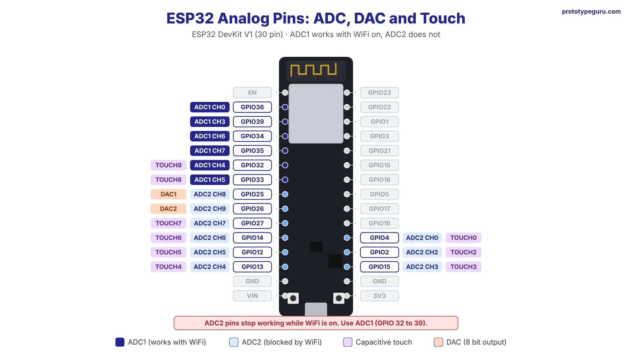
ADC1 vs ADC2 (and Why ADC2 Fails With WiFi)
The ESP32 has two 12 bit ADCs. A 12 bit reading runs from 0 to 4095, where 4095 matches the top of the input range.
| ADC | GPIO pins on the DevKit | Works with WiFi on? |
|---|---|---|
| ADC1 | 32, 33, 34, 35, 36, 39 | Yes |
| ADC2 | 0, 2, 4, 12, 13, 14, 15, 25, 26, 27 | No |
The WiFi driver takes over ADC2. Once WiFi starts, analogRead() on an ADC2 pin fails or returns junk, and the Espressif ADC documentation confirms this limit. For any WiFi project, put analog sensors on ADC1, which gives you six pins on a DevKit board.
The ESP32 ADC also bends near the ends of its range, so readings flatten close to 0 V and again close to 3.3 V. Annoying, but fixable. In Arduino code, analogReadMilliVolts() applies the factory calibration and returns millivolts, which beats converting raw counts yourself.
DAC Pins (GPIO 25 and 26)
GPIO 25 and GPIO 26 output a real analog voltage through two 8 bit DACs, with values from 0 to 255, so dacWrite(25, 128) gives you about 1.65 V. Good for audio tones and test signals. Newer chips such as the ESP32 S3 and C3 dropped the DAC, which makes these two pins a good reason to stay on the classic chip.
Capacitive Touch Pins
Ten GPIOs can sense a finger through a copper pad or a wire, with no button needed.
| Touch | GPIO | Touch | GPIO |
|---|---|---|---|
| T0 | 4 | T5 | 12 |
| T1 | 0 | T6 | 14 |
| T2 | 2 | T7 | 27 |
| T3 | 15 | T8 | 33 |
| T4 | 13 | T9 | 32 |
touchRead(4) returns a number that drops when you touch the pad, and the same pins can wake the chip from deep sleep. Skip T1, T2, T3 and T5 for touch pads if you can, because those sit on strapping pins.
ESP32 Communication Pins: I2C, SPI and UART
The ESP32 routes most peripherals through a GPIO matrix, described in the ESP32 Technical Reference Manual, which means you can move I2C, SPI and UART to almost any output pin. Defaults still matter. Most libraries and tutorials expect them.
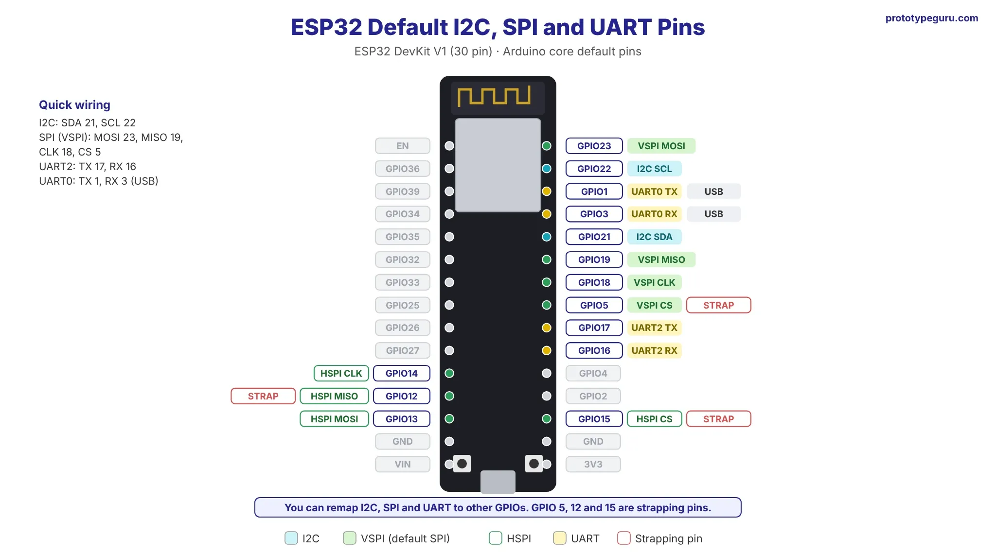
| Bus | Signal | Default GPIO |
|---|---|---|
| I2C | SDA / SCL | 21 / 22 |
| VSPI (default SPI) | MOSI / MISO / CLK / CS | 23 / 19 / 18 / 5 |
| HSPI | MOSI / MISO / CLK / CS | 13 / 12 / 14 / 15 |
| UART0 (USB) | TX / RX | 1 / 3 |
| UART2 | TX / RX | 17 / 16 |
New to these buses? Our guide on I2C vs SPI vs UART explains how each one works and where it fits.
I2C Pins
The ESP32 has two I2C controllers. Wire.begin() uses GPIO 21 for SDA and GPIO 22 for SCL. To pick other pins, pass them in: Wire.begin(25, 26).
I2C lines need pull up resistors to 3.3 V. Many sensor breakout boards include them already, and if you stack three or four of those boards on one bus, the resistors sit in parallel and the total drops too low for clean signals. Our I2C pull up resistor calculator finds the right value.
SPI Pins (VSPI and HSPI)
Two SPI buses are free for your use, VSPI and HSPI. The Arduino SPI library defaults to VSPI on GPIO 23, 19, 18 and 5. HSPI sits on GPIO 13, 12, 14 and 15, and two of those (GPIO 12 and 15) are strapping pins. An SD card module on HSPI can stop the board from booting, so start with VSPI and add chip select pins on safe GPIOs for extra devices.
UART Pins
The ESP32 has three UARTs. UART0 on GPIO 1 and 3 talks to the USB chip, so the Serial Monitor and code uploads use it. UART1 is trickier. Its default pins, GPIO 9 and 10, are flash pins, so remap it before use. For GPS modules and other serial devices, UART2 on GPIO 16 and 17 is the easy choice:
Serial2.begin(9600, SERIAL_8N1, 16, 17); // RX = 16, TX = 17Baud rate mismatches cause most garbled serial output. Our baud rate calculator checks timing and error for common rates.
ESP32 PWM, Interrupts and RTC GPIOs
Any ESP32 pin that can output can also produce PWM, so GPIO 34 to 39 are the only pins left out. The LEDC peripheral gives you 16 PWM channels with adjustable frequency and resolution.
Arduino core 3.x changed the PWM functions. The old ledcSetup() and ledcAttachPin() calls are gone, and the pin now replaces the channel number. The Arduino ESP32 migration guide lists the changes:
// Arduino ESP32 core 3.x
ledcAttach(25, 5000, 8);   // pin, frequency in Hz, resolution in bits
ledcWrite(25, 128);        // about 50% duty cycle
Core 3.x also removed hallRead(), so older tutorials that read the built in Hall sensor won’t compile. If your sketch throws errors on these functions, check your core version under Tools > Board > Boards Manager.
Interrupts work on all GPIO pins. Use attachInterrupt(digitalPinToInterrupt(27), onPress, FALLING) and keep the handler short.
RTC GPIOs stay alive in deep sleep and can wake the chip. The classic ESP32 has 18 of them: GPIO 0, 2, 4, 12 to 15, 25 to 27 and 32 to 39. Use one for a wake button or a motion sensor. The bare chip draws about 10 µA in deep sleep with the RTC timer running, though a DevKit board draws far more because of its regulator and USB chip. Our low power circuit design guide covers how to close that gap on your own board.
ESP32 Pinout Tips for Custom PCB Design
A DevKit is fine on a breadboard. Once a project moves to its own PCB, the ESP32 pinout turns into layout decisions. These are the rules we check on ESP32 boards before they go to fabrication, and they follow the Espressif hardware design guidelines.
Leave the WROOM pads for GPIO 6 to 11 unconnected. Route nothing to them.
Give GPIO 0 a 10 kΩ pull up and a BOOT button to ground. On EN, a 10 kΩ pull up and a 1 µF capacitor hold the chip in reset until the supply settles, which stops random boot failures on slow power supplies and battery packs. GPIO 12 gets no pull up. Keep GPIO 2 LOW or floating at boot.
Bring out GPIO 0, EN, TX0, RX0, 3V3 and GND to a six pin header. That header lets you flash and debug the board with a USB to serial adapter, even with no USB chip on the board. For deeper debugging on newer chips, see our guide on JTAG debugging on ESP32 S3.
Keep copper, parts and ground pour away from the module antenna, and let the antenna end hang over the board edge where you can. Our 2.4 GHz PCB antenna design guide explains the keepout rules.
Place a 10 µF and a 100 nF capacitor right at the module’s 3V3 pad. Thin power traces plus no bulk capacitance? WiFi bursts will reset that board.
Our ESP32 PCB design guide covers layout, stackup and power in full.
If a project needs native USB or more GPIOs, a newer chip may suit it better:
| Feature | ESP32 (classic) | ESP32 S3 | ESP32 C3 |
|---|---|---|---|
| CPU | Dual core LX6, 240 MHz | Dual core LX7, 240 MHz | Single core RISC V, 160 MHz |
| GPIO | 34 | 45 | 22 |
| DAC | 2 | None | None |
| Touch | 10 | 14 | None |
| Bluetooth | 4.2 Classic and BLE | BLE 5 | BLE 5 |
| Native USB | No | Yes | Yes (Serial/JTAG) |
The S3 and C3 have their own pinouts and strapping pins, so don’t reuse this table for them. We’ll cover both in separate guides.
ESP32 Pinout FAQs
What pins to avoid on ESP32?
Avoid GPIO 6 to 11, because they connect to the flash chip. Be careful with the strapping pins, GPIO 0, 2, 5, 12 and 15, since they set the boot mode. GPIO 34 to 39 work as inputs only. GPIO 1 and 3 carry USB serial, so using them blocks the Serial Monitor.
How many GPIO pins does the ESP32 have?
The ESP32 chip has 34 GPIO pins. A 30 pin DevKit V1 breaks out 25 of them, and a 38 pin DevKitC breaks out 32, including the six flash pins. After you remove flash, input only and strapping pins, about 15 general purpose pins remain.
What is the difference between ESP32 30 pin and 38 pin?
The 38 pin board adds GPIO 0, the six flash pins (GPIO 6 to 11), a 5V pin and an extra GND. The flash pins aren’t usable, so the real gain is GPIO 0. The 30 pin board is narrower, so it fits a standard breadboard with a free row on each side.
How do I configure the GPIO pins on an ESP32?
In Arduino code, call pinMode(pin, OUTPUT), pinMode(pin, INPUT) or pinMode(pin, INPUT_PULLUP) in setup(). Then use digitalWrite() and digitalRead(). Use the GPIO number, so GPIO 23 is pinMode(23, OUTPUT). In Espressif’s own IDF framework, use gpio_config() as shown in the Espressif GPIO documentation.
What is ESP32 used for?
People use the ESP32 for WiFi and Bluetooth projects: smart home devices, sensor nodes, data loggers, BLE beacons, web servers and wearables. It suits battery products too, thanks to its deep sleep modes. Browse our ESP32 sensor and module guides for project ideas.
Is ESP32 5V tolerant?
No. Espressif rates the ESP32 for 3.3 V logic with a 3.6 V maximum supply. A 5 V signal can damage a GPIO pin over time. Use a level shifter or a resistor divider for 5 V sensors and modules.
Conclusion
A good ESP32 pinout reference comes down to a few rules. Use the safe GPIOs first, keep GPIO 6 to 11 unconnected, put analog sensors on ADC1 if WiFi runs, and keep the strapping pins in their default state at boot. Most boards that look dead after wiring have one of these pins in the wrong state.
Print the PDF, keep the GPIO table open while you wire, and check your board’s silkscreen. Ready to move a breadboard prototype onto a custom board? Start with our ESP32 PCB design guide, then send us your design for a review.